


Outputs and Digital Input
Configuring Analog Output
VT200/220 Technical Manual, Rev 1.00.01
67
Doc
#
TM-VT200/220-EN
7.4.1
Connecting PCB and Setting Jumper
In order to use analog output, the option PCB (PCB 761) connected it to the VT200 as
follows: In the one side to
ST5
socket
on the main board
and in the other side using
the mounting posts/spacers provided to:
Stainless steel enclosure
– Main board.
Aluminum enclosure
– Indicator’s rear panel (see page 80).
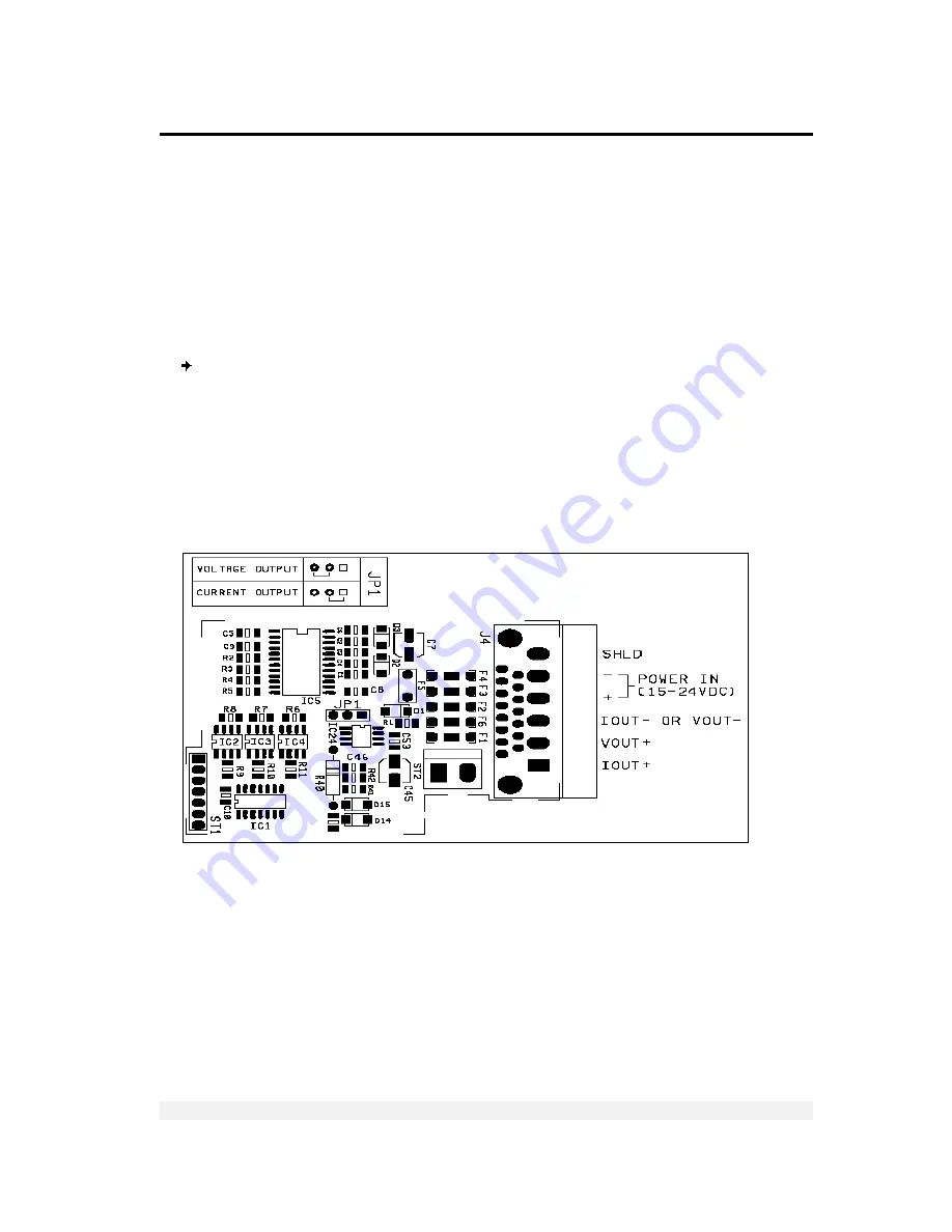
Jumper JP1 determines the output mode – current or voltage.
Analog
output
pins
connections:
1. Connect pins as follows:
For current output, connect pin 1 (current output, +) and pin 3 (common).
For voltage output, connect pin 2 (voltage output, +) and pin 3 (common).
2. Connect an external power supply of 24VDC, using pins 4 and 5:
Pin 4 – power in (+).
Pin 5 – power in (-).