CGAD-SVN02C-EN
11
Application Considerations
Certain application restrictions should be
taken into consideration as for the size,
selection, and installation of the CGAD
liquid chillers with air condensation from
Trane. The reliability of the unit and system
many times depends on the appropriate
and complete agreement with these
conditions. Applications that vary from the
guidelines given must be reviewed by your
local Trane engineer.
Dimensioning of the Unit
The unit's capacities are listed in the
section of performance data. To
intentionally overdimension a unit to
ensure adequate capacity is not
recommended. The excess in calculating
the capacity of the system and
compressor has a direct result of an
overdimensioned liquid chiller.
Furthermore, an overdimensioned unit is
normally more expensive to purchase,
install, and operate. If overdimensioning is
desired, consider using two units.
Installing the Unit
Adjusting the Unit
A base or foundation is not necessary if the
location selected for the unit is level and
solid enough to withstand the unit's
operational weight, which is listed in the
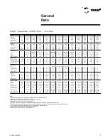
table of general data (operational weight).
Insulation and Noise Emission
The most effective way to provide
insulation is to put the unit far away from
any sound-sensitive area. Noise
transmitted structurally can be reduced by
eliminating vibrations. Spring insulators
have shown to be not very effective in
installations with CGAD liquid chillers with
air condensation and we do not
recommend them.
An engineer specialized in this area
should be called upon for advice with
critical sound level applications.
For a maximum insulation effect, water
lines and electric ducts should also be
insulated. Sleeves for the passing of tubes
through walls and king posts of insulated
tubing with rubber can be used to reduce
the noise transmitted by the water tubing.
In order to reduce the noise transmitted
through electric ducts, use flexible ducts.
State and local laws about noise emission
must always be taken into consideration.
Since the environment in which a noise
source is located affects the sound
pressure, where the unit is placed should
be carefully evaluated.
Maintenance
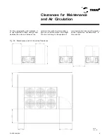
Adequate clearance for maintenance on
the evaporator and the compressor must
be provided. The minimum space
recommended for maintenance may be
found in the section of dimensional data
and it can serve as guidelines to provide
adequate clearance. The minimum space
also gives enough room to open the
control panel and to carry out routine
maintenance.
Location of the Unit
General
An unobstructed air flow in the condenser
is essential to maintain the liquid chiller's
operational capacity and efficiency. When
deciding where to put the unit, some
careful considerations should be taken
into account in order to ensure enough air
flow through the condenser's heat transfer
Application
Considerations
surface. Two conditions may occur that
must be avoided if optimum performance
is going to be reached: short circuit of hot
air and scarcity of air circulation in the coil.
The short circuiting of hot air occurs when
the air flow from the condenser fans is
blown to the entrance of the condenser's
coil caused by some restriction in the
place of installation.
The lack of air circulation on the coil occurs
when the free air flow to the condenser coil
is restricted. Both the short circuiting of hot
air as well as the lack of free air flow
around the coil cause reductions in the
unit's efficiency and capacity due to the
high discharge pressures associated with
these.
Summary of Contents for CGAD020
Page 36: ...CGAD SVN02C EN 36 Wiring Diagram Fig 17 Power and command wiring diagram CGAD 020C Sheet 1 2...
Page 52: ...CGAD SVN02C EN 52 Wiring Diagram Fig 33 Power and command wiring diagram CGAD 070C Sheet 1 2...
Page 60: ...CGAD SVN02C EN 60 Wiring Diagram Fig 41 Power and command wiring diagram CGAD100 Part I...
Page 61: ...CGAD SVN02C EN 61 Wiring Diagram Fig 42 Power and command wiring diagram CGAD100 Part II...
Page 62: ...CGAD SVN02C EN 62 Wiring Diagram Fig 43 Power and command wiring diagram CGAD100 Part III...
Page 63: ...CGAD SVN02C EN 63 Wiring Diagram Fig 44 Layout diagram CGAD100...
Page 64: ...CGAD SVN02C EN 64 Wiring Diagram Fig 45 Power and command wiring diagram CGAD120 Part I...
Page 65: ...CGAD SVN02C EN 65 Wiring Diagram Fig 46 Power and command wiring diagram CGAD120 Part II...
Page 66: ...CGAD SVN02C EN 66 Wiring Diagram Fig 47 Power and command wiring diagram CGAD 120 Part III...
Page 67: ...CGAD SVN02C EN 67 Wiring Diagram Fig 48 Layout diagram CGAD 120...
Page 68: ...CGAD SVN02C EN 68 Wiring Diagram Fig 49 Power and command wiring diagram CGAD150 Part I...
Page 69: ...CGAD SVN02C EN 69 Wiring Diagram Fig 50 Power and command wiring diagram CGAD150 Part II...
Page 70: ...CGAD SVN02C EN 70 Wiring Diagram Fig 51 Power and command wiring diagram CGAD150 Part III...
Page 71: ...CGAD SVN02C EN 71 Fig 52 Layout diagram CGAD150 Wiring Diagram...
Page 72: ...CGAD SVN02C EN 72 Wiring Diagram Fig 53 Layout diagram CGAD 100 125 150 with optionals...


