CGAD-SVN02C-EN
33
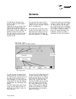
Basic Screen Format
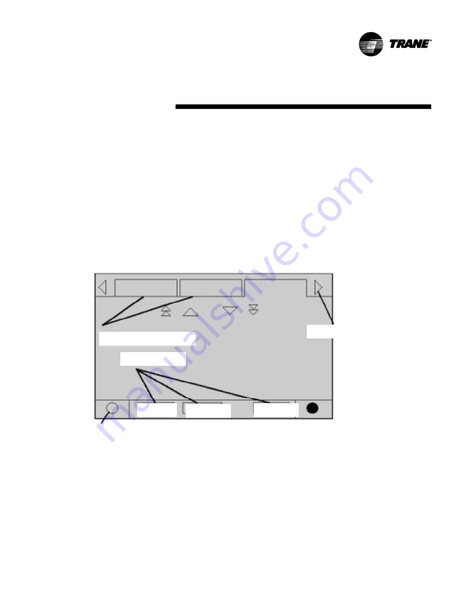
The screen's format is basically as follows:
Browser
Radio button
Folder tabs
Auto
Stop
Alarms
Control adjustment
The AUTO and STOP buttons have priority
in relation to the keys Enter and Cancel.
(During a program change, the AUTO and
STOP buttons are recognized even if the
buttons Enter or Cancel are pushed).
The button ALARMS comes up only when
there is the presence of an alarm, and
then it blinks (alternating from normal to
strong) in order to point out a diagnostic
situation. If the ALARM button is pushed,
the corresponding tab will open giving
additional information.
The other functions are essential for the
machine's operation. The buttons AUTO
and STOP are used to start-up and turn off
the chiller. The key selected is shown in
black (highlighted). The chiller stops when
touching the STOP button after it finishes
the operational mode of discharge (RUN
MODE).
The AUTO button puts the chiller in active
cooling if no other diagnostic exists. (An
additional action is needed to erase the
active diagnostic).
The folder tabs on the top part of the
screen are used to select the different
types of screens.
Displacement arrows are added if more
tabs (options) are available. When the
tables are all to the left, the navigator on the
left side does not show up, making it only
possible to browse to the right. In the
same way, when the screen all the way to
the right is selected, you can then only
browse to the left.
The main part of the screen is used for
descriptive texts, data, levels of reference,
or keys (touch area). The chiller mode (see
table 1) is presented here.
The double arrows up and down are for
moving up or down a page at a time. The
single arrows are for going up or down a
line at a time. At the end of the page, the
respective displacement bar disappears.
The lower part of the screen (fixed display)
is shown on all the screens and contains
the following functions. The left circular
zone is used to reduce the contrast/angle
for visualizing the display. The right circular
zone is used to increase the contrast/
angle of the display's visualization. This
configuration may result on different
temperatures from the last configuration.
Screens
Summary of Contents for CGAD020
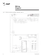
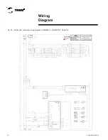
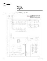
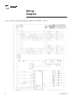
Page 36: ...CGAD SVN02C EN 36 Wiring Diagram Fig 17 Power and command wiring diagram CGAD 020C Sheet 1 2...
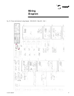
Page 52: ...CGAD SVN02C EN 52 Wiring Diagram Fig 33 Power and command wiring diagram CGAD 070C Sheet 1 2...
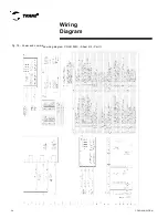
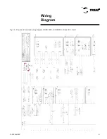
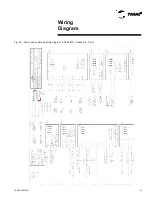
Page 60: ...CGAD SVN02C EN 60 Wiring Diagram Fig 41 Power and command wiring diagram CGAD100 Part I...
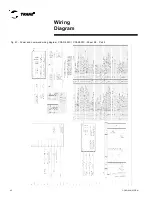
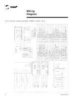
Page 61: ...CGAD SVN02C EN 61 Wiring Diagram Fig 42 Power and command wiring diagram CGAD100 Part II...
Page 62: ...CGAD SVN02C EN 62 Wiring Diagram Fig 43 Power and command wiring diagram CGAD100 Part III...
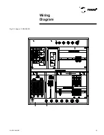
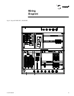
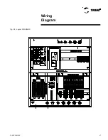
Page 63: ...CGAD SVN02C EN 63 Wiring Diagram Fig 44 Layout diagram CGAD100...
Page 64: ...CGAD SVN02C EN 64 Wiring Diagram Fig 45 Power and command wiring diagram CGAD120 Part I...
Page 65: ...CGAD SVN02C EN 65 Wiring Diagram Fig 46 Power and command wiring diagram CGAD120 Part II...
Page 66: ...CGAD SVN02C EN 66 Wiring Diagram Fig 47 Power and command wiring diagram CGAD 120 Part III...
Page 67: ...CGAD SVN02C EN 67 Wiring Diagram Fig 48 Layout diagram CGAD 120...
Page 68: ...CGAD SVN02C EN 68 Wiring Diagram Fig 49 Power and command wiring diagram CGAD150 Part I...
Page 69: ...CGAD SVN02C EN 69 Wiring Diagram Fig 50 Power and command wiring diagram CGAD150 Part II...
Page 70: ...CGAD SVN02C EN 70 Wiring Diagram Fig 51 Power and command wiring diagram CGAD150 Part III...
Page 71: ...CGAD SVN02C EN 71 Fig 52 Layout diagram CGAD150 Wiring Diagram...
Page 72: ...CGAD SVN02C EN 72 Wiring Diagram Fig 53 Layout diagram CGAD 100 125 150 with optionals...

