CGAD-SVN02C-EN
6
Unit Inspection
Upon receiving the unit at the installation
site, proceed as follows:
- Make sure that the data on the nameplate
are the same as the data contained on the
sales order and shipping invoice
(including electrical data).
- Make sure that the local power supply
conditions comply with the specifications
on the identification plate.
- Carefully inspect the unit for damages
occurred during transportation. Report any
damage or material shortage immediately
to the carrier. Make a “unit damage”on the
carrier’s delivery receipt. Specify the type
and extend of damage.
- Notify Trane do Brasil and/or the
installation company about the damages
and the actions required for repairs. Do not
repair the unit until the damages have
been inspected.
Storage
If the unit cannot be installed in its
permanent location at the time of delivery,
store it in a safe place, and protect it from
exposure to the wheater and other factors
that may damage it. Storage, as well as
inappropriate moving of the equipment,
will imply in the equipment losing its
warranty.
Instructions for proper installation
Consider the following items for a correct
installation before placing the unit in its
location:
- The floor and unit base should be level,
solid, and strong enough to bear the
Unit Inspection
weight of the unit and its accessories.
Level or repair the floor at the location
where the unit will be installed before
placing it.
- Make sure units have rubber skids or
vibration isolators.
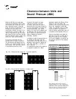
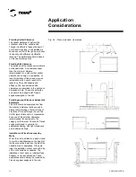
- Provide the minimum clearances
recommended for routine maintenance
and services; see page 12 of this manual.
- The same distances apply in case of
various units together.
- Provide the electrical installation. The
units are designed so that they can receive
electrical hookups from either side.
- Make sure there is enough space for the
piping and to remove the covers.
- The supply of electrical power should
comply with the Norm NBR 5410 and local
and/or NEC codes.
- The installer should provide and install
the hydraulic piping to connect the air-
conditioning units to the CGAD liquid
chiller.
General Safety
CGAD units are designed to work safely
and in a reliable manner when operated
according to the safety norms. The system
works with electrical, mechanical, water
and gas pressure components, as well as
many other components that can cause
personal damage to people and
equipment if they do not comply with the
needed safety norms.
Therefore, only specialized and/or Trane-
authorized installers should carry out
installation, start-up, and maintenance on
this type of equipment.
Follow all the safety regulations related to
the work and the warning signs on the
stickers placed on the units, and always
use appropriate tools and equipment.
Identifying Danger
WARNING!
!
Warnings appear at appropriate
locations throughout this manual in
order to alert operators and service
personnel about situations of
potential risk that COULD result in
severe personal injury or damage to
the equipment if safety regulations
are not followed.
!
Cautions appear at appropriate
locations throughout this manual in
order to alert operators and service
personnel about situations of
potential risk that could damage the
equipment or the environment.
CAUTION:
Summary of Contents for CGAD020
Page 36: ...CGAD SVN02C EN 36 Wiring Diagram Fig 17 Power and command wiring diagram CGAD 020C Sheet 1 2...
Page 52: ...CGAD SVN02C EN 52 Wiring Diagram Fig 33 Power and command wiring diagram CGAD 070C Sheet 1 2...
Page 60: ...CGAD SVN02C EN 60 Wiring Diagram Fig 41 Power and command wiring diagram CGAD100 Part I...
Page 61: ...CGAD SVN02C EN 61 Wiring Diagram Fig 42 Power and command wiring diagram CGAD100 Part II...
Page 62: ...CGAD SVN02C EN 62 Wiring Diagram Fig 43 Power and command wiring diagram CGAD100 Part III...
Page 63: ...CGAD SVN02C EN 63 Wiring Diagram Fig 44 Layout diagram CGAD100...
Page 64: ...CGAD SVN02C EN 64 Wiring Diagram Fig 45 Power and command wiring diagram CGAD120 Part I...
Page 65: ...CGAD SVN02C EN 65 Wiring Diagram Fig 46 Power and command wiring diagram CGAD120 Part II...
Page 66: ...CGAD SVN02C EN 66 Wiring Diagram Fig 47 Power and command wiring diagram CGAD 120 Part III...
Page 67: ...CGAD SVN02C EN 67 Wiring Diagram Fig 48 Layout diagram CGAD 120...
Page 68: ...CGAD SVN02C EN 68 Wiring Diagram Fig 49 Power and command wiring diagram CGAD150 Part I...
Page 69: ...CGAD SVN02C EN 69 Wiring Diagram Fig 50 Power and command wiring diagram CGAD150 Part II...
Page 70: ...CGAD SVN02C EN 70 Wiring Diagram Fig 51 Power and command wiring diagram CGAD150 Part III...
Page 71: ...CGAD SVN02C EN 71 Fig 52 Layout diagram CGAD150 Wiring Diagram...
Page 72: ...CGAD SVN02C EN 72 Wiring Diagram Fig 53 Layout diagram CGAD 100 125 150 with optionals...


