CGAD-SVN02C-EN
14
Application
Considerations
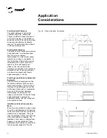
Typical Water Piping
All the water pipes in the building should
be clean before making the final
connections with the liquid chiller. In order
to reduce heat loss and prevent
condensation, insulation should be
installed. Normally expansion tanks are
also needed so that changes in the chilled
water volume can be accommodated.
Operation in Series
Some systems require large drops in
chilled water temperature (8.8 to 13.3oC).
For these installations, two units are
needed with their evaporators in series.
The control of the units should begin with
the single temperature controller in order to
keep the separate thermostats from
opposing each other in a single "take". It is
possible to control the units from the
individual controls of the units, but a single
temperature controller provides a positive
method for preventing the overlapping of
controls, it balances the system's load
more appropriately, and simplifies the lead-
lag capacity for the compressor.
Parallel Operation
Some systems ask for more capacity or
reserve capacity that a simple machine can
offer. For these installations, two units with
their evaporators in a parallel configuration
are common. A single effective method of
controlling two units in parallel is with a
single temperature controller. Two
individual temperature controls are not
capable of providing a reliable control of the
system and will result in an unsatisfactory
operation and possible failure in the
compressor.
Water Circuit that is too Small
The appropriate localization of the
temperature control sensor is at the water
supply (outlet). This location makes it so
that the building serves as a kind of buffer
and ensures a slow changeover in the
return water temperature. If there is not a
sufficiently large enough water volume in
the system to supply an adequate buffer,
the temperature control may be lost,
resulting in a subdimensioning of the
liquid chiller. A water circuit that is too small
has the same effect of trying to control the
system from the return water point forward.
Minimal water volume is given by following
equation
Minimal Volume = GPM x 3 filling time
GPM = Gallons per minute
As a general guideline, a tank must be
added to system if the volume of water is
too low. Make sure that the water volume in
the evaporator's circuit is equal to or two
times greater than the evaporator's flow.
For a quick change in the charge profile,
the volume should be increased. In order
to avoid the effects of a water circuit that is
too small, special attention should be
given to the following items: A storage tank
or a large pipe to increase the volume of
water in the system and this way reduce
the temperature changeover rate of the
return water.
Operation of Multiple Units
Whenever two or more units are used in a
chilled water circuit, Trane recommends
that their operations be controlled by a
single control device.
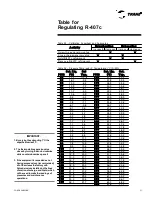
Height
Capacity
Consumption
Water Flow
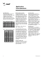
0
1.000
1.000
1.000
500
997
1.012
997
1000
994
1.024
994
1500
991
1.037
991
2000
987
1.052
987
2500
983
1.067
983
3000
978
1.084
978
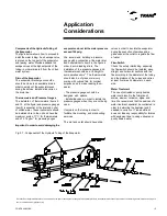
Recomended de
Etileno Glicol %
°F
°C
40
4,4
0
39
3,9
3
38
3,3
6
37
2,8
8
36
2,2
10
35
1,7
12
34
1,1
14
33
0,6
15
32
0,0
17
31
-0,6
19
30
-1,1
20
29
-1,7
21
28
-2,2
23
27
-2,8
25
26
-3,3
26
Water Outlet
Temperature
Tab. 03 - Recomended de Etileno Glicol %
Tab. 02 - Height Correctors Factors
Summary of Contents for CGAD020
Page 36: ...CGAD SVN02C EN 36 Wiring Diagram Fig 17 Power and command wiring diagram CGAD 020C Sheet 1 2...
Page 52: ...CGAD SVN02C EN 52 Wiring Diagram Fig 33 Power and command wiring diagram CGAD 070C Sheet 1 2...
Page 60: ...CGAD SVN02C EN 60 Wiring Diagram Fig 41 Power and command wiring diagram CGAD100 Part I...
Page 61: ...CGAD SVN02C EN 61 Wiring Diagram Fig 42 Power and command wiring diagram CGAD100 Part II...
Page 62: ...CGAD SVN02C EN 62 Wiring Diagram Fig 43 Power and command wiring diagram CGAD100 Part III...
Page 63: ...CGAD SVN02C EN 63 Wiring Diagram Fig 44 Layout diagram CGAD100...
Page 64: ...CGAD SVN02C EN 64 Wiring Diagram Fig 45 Power and command wiring diagram CGAD120 Part I...
Page 65: ...CGAD SVN02C EN 65 Wiring Diagram Fig 46 Power and command wiring diagram CGAD120 Part II...
Page 66: ...CGAD SVN02C EN 66 Wiring Diagram Fig 47 Power and command wiring diagram CGAD 120 Part III...
Page 67: ...CGAD SVN02C EN 67 Wiring Diagram Fig 48 Layout diagram CGAD 120...
Page 68: ...CGAD SVN02C EN 68 Wiring Diagram Fig 49 Power and command wiring diagram CGAD150 Part I...
Page 69: ...CGAD SVN02C EN 69 Wiring Diagram Fig 50 Power and command wiring diagram CGAD150 Part II...
Page 70: ...CGAD SVN02C EN 70 Wiring Diagram Fig 51 Power and command wiring diagram CGAD150 Part III...
Page 71: ...CGAD SVN02C EN 71 Fig 52 Layout diagram CGAD150 Wiring Diagram...
Page 72: ...CGAD SVN02C EN 72 Wiring Diagram Fig 53 Layout diagram CGAD 100 125 150 with optionals...


