CGAD-SVN02C-EN
19
Calculating Subcooling
and Superheat
Superheat Adjustments
Superheat is checked and adjusted in the
following way:
- In order to analyze the superheat
condition, the surface of the tubing should
be prepared where the temperature
sensor will be connected by sanding the
surface and the fastening area.
- Securely fasten the sensor of a precise
electronic thermometer to the suction line
close to the remote bulb of the thermostatic
expansion valve on the same plane
(Suction Line Temperature - SLT). Insolate
the sensor with adhesive tape in order to
keep out the interference of external
temperatures.
- Open the valve of the low pressure
manometer on the suction side of the
equipment.
- Turn on the system and allow the
temperature shown on the thermometer to
stabilize after the equipment has been on
for a while.
- Convert what is shown on the
manometer into °C, using the saturation
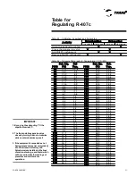
table for R-407C. The difference in
degrees between the thermometer
marking and the saturated evaporating
temperature (SEVT) is the value of
superheat. If superheat is greater than
10°C or less than 6°C, continue with this
step.
SUP = TLS - TEVS
- Remove the lid to the body of the
expansion valve and make the needed
adjustment by turning the calibration rod.
- For superheat greater than 10°C, open
the expansion valve or add refrigerant.
- For superheat less than 6°C, close the
expansion valve or remove refrigerant.
- After the adjustment is made, remove the
sensor of the electronic thermometer and
isolate once again the suction line.
- Close the valve of the manometer for low
pressure.
Subcooling Adjustments
Subcooling is checked and adjusted in the
following way:
- In order to analyze the subcooling
condition, the surface of the tubing should
be prepared where the temperature
sensor will be connected by sanding the
surface and the fastening area.
- Securely fasten the sensor of a precise
electronic thermometer to the liquid line,
10 to 15 cm before the unit's filter dryer on
the same plane (Liquid Line Temperature
- LLT). Insolate the sensor with adhesive
tape in order to keep out the interference of
external temperatures.
- Open the valve of the high pressure
manometer on the side of the
compressor's discharge, if the unit has
one. A more exact reading will be obtained
by measuring the high pressure at the
Schrader valve on the liquid line.
- Turn on the system and allow the
temperature shown on the thermometer to
stabilize after the equipment has been on
for a while.
- Convert what is shown on the
manometer into °C, using the saturation
table for R-407C. The difference in
degrees between the saturated
condensing temperature (SCDT) and the
marking of the electronic thermometer is
the subcooling level. If subcooling is
greater than 10°C or less than 5°C,
continue with this step.
SUB = TCDS - TLL
- Remove the lid of the Schrader valve on
the liquid line close to the solenoid valve
and install a refrigeration hose on the
pressure tap that is equipped with a
bellows valve. If the subcooling is greater
than 10°C, evacuate refrigerant from the
system until the subcooling is calibrated or
open the expansion valve.
- If the subcooling is less than 5°C, charge
refrigerant through the suction valve of the
system's compressor until the ideal
subcooling conditions is reached or close
the expansion valve.
- After the adjustment is made, remove the
sensor of the electronic thermometer that
was previously fixed there.
- Close the valve of the manometer for
high pressure.
WARNING!
!
Never put flame to the refrigerant
cylinder to increase its pressure.
Uncontrolled heat may cause an
excessive pressure and an explosion
that could result in injuries, death, and the
damaging of the equipment.
Note:
1. When the subcooling varies 1°C, the
superheat varies 3°C.
2. The thermostatic expansion valve
closes by turning the knob clockwise,
while counterclockwise opens it
CAUTION:
!
Do not operate the compressor without
some quantity of refrigerant present in
the circuit. The compressors could be
damaged.
CAUTION:
!
1. Weigh the refrigerant cylinder before
and after the charge.
2. Do not allow the refrigerant liquid to get
into the suction line. Liquid in excess
could damage the compressor.
WARNING!
!
1. In order to avoid injuries from freezing,
do not have direct contact with the
refrigerant.
2. Use Personal SafetyEquipment during
all procedures.
Summary of Contents for CGAD020
Page 36: ...CGAD SVN02C EN 36 Wiring Diagram Fig 17 Power and command wiring diagram CGAD 020C Sheet 1 2...
Page 52: ...CGAD SVN02C EN 52 Wiring Diagram Fig 33 Power and command wiring diagram CGAD 070C Sheet 1 2...
Page 60: ...CGAD SVN02C EN 60 Wiring Diagram Fig 41 Power and command wiring diagram CGAD100 Part I...
Page 61: ...CGAD SVN02C EN 61 Wiring Diagram Fig 42 Power and command wiring diagram CGAD100 Part II...
Page 62: ...CGAD SVN02C EN 62 Wiring Diagram Fig 43 Power and command wiring diagram CGAD100 Part III...
Page 63: ...CGAD SVN02C EN 63 Wiring Diagram Fig 44 Layout diagram CGAD100...
Page 64: ...CGAD SVN02C EN 64 Wiring Diagram Fig 45 Power and command wiring diagram CGAD120 Part I...
Page 65: ...CGAD SVN02C EN 65 Wiring Diagram Fig 46 Power and command wiring diagram CGAD120 Part II...
Page 66: ...CGAD SVN02C EN 66 Wiring Diagram Fig 47 Power and command wiring diagram CGAD 120 Part III...
Page 67: ...CGAD SVN02C EN 67 Wiring Diagram Fig 48 Layout diagram CGAD 120...
Page 68: ...CGAD SVN02C EN 68 Wiring Diagram Fig 49 Power and command wiring diagram CGAD150 Part I...
Page 69: ...CGAD SVN02C EN 69 Wiring Diagram Fig 50 Power and command wiring diagram CGAD150 Part II...
Page 70: ...CGAD SVN02C EN 70 Wiring Diagram Fig 51 Power and command wiring diagram CGAD150 Part III...
Page 71: ...CGAD SVN02C EN 71 Fig 52 Layout diagram CGAD150 Wiring Diagram...
Page 72: ...CGAD SVN02C EN 72 Wiring Diagram Fig 53 Layout diagram CGAD 100 125 150 with optionals...

