CGAD-SVN02C-EN
15
Application
Considerations
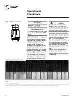
Components of the Hydraulic Tubing of
the Evaporator
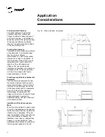
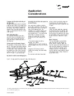
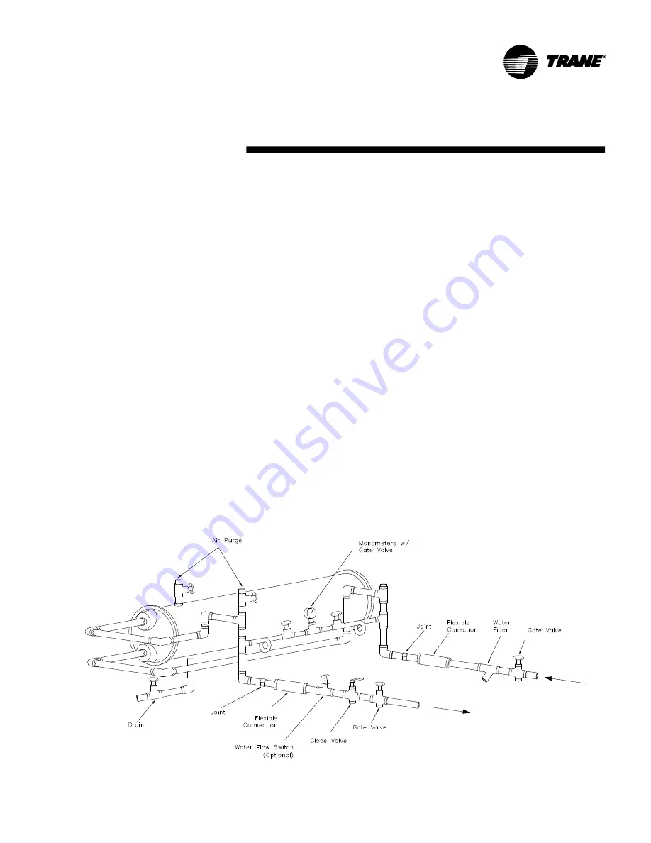
The figure below shows how to proceed to
install the water tubing. An air escape valve
is placed on the top part of the evaporator
and leaving water. Provide additional air
escape valves at the highest points of the
tubing in order eliminate it from the chilled
water system.
Drain of the Evaporator
The evaporator discharge connection
should be close to an available drain in
order to empty out the evaporator even
during the service. Install a slide valve on
the drain line.
Thermometers and Pressure Gauges
The installation of thermometers (items 5
and 12 of the figure) and pressure gauges
(item 9) is essential at the inlet and outlet
of chilled water. These instruments should
be installed close to the unit and have the
maximum scale of 1
o
C for thermometers
and of 0.1 kg/cm
2
for pressure gauges.
Important: In order to avoid damaging the
evaporator, do not let the water pressure
exceed 150 psig.
We recommend installing a pressure
gauge with a connection at the water inlet
and outlet similar to item 9 in the figure in
order to avoid reading errors. The
installation of the pressure gauges and
thermometers should be at a height to
avoid parallax errors*. The thermometers
should also be of glass or mercury
scaling with colored fluid for contrast
purposes and to make reading them
easier.
- The pressure gauges should be
designed with siphons.
- Install slide valves in order to isolate the
pressure gauges when they are not being
used.
Use joints on the tubing in order to
facilitate the mounting and dismounting
services.
The inlet and outlet should have slide
valves in order to insolate the evaporator
during the execution of services and a
globe valve at the outlet to regulate the flow
of water.
Flow-Switch
Check the safety interlocking, especially
the flow-switch should be installed along
straight and horizontal sections with the
fins according to the diameter of the tubing
and the distance of the curves and valves
at least five times its diameter on each
side.
Water Treatment
The use of untreated or poorly treated
water could result in the formation of
scales, erosion, corrosion, algae, and
lime. We recommend that the services of a
water treatment specialist be contracted in
order to determine the treatment and if
needed, to carry it out. Trane do Brasil
does not take any responsibility for failures
with equipment due to using untreated or
poorly treated water.
* Parallax Error: Apparent dislocation of an object when the point of observation is changed. This especially refers to the apparent dislocation of the needle of a measuring instrument when looking at it
from a vertical direction (parallax error).
Fig. 07 - Components of the Hydraulic Tubing of the Evaporator
Summary of Contents for CGAD020
Page 36: ...CGAD SVN02C EN 36 Wiring Diagram Fig 17 Power and command wiring diagram CGAD 020C Sheet 1 2...
Page 52: ...CGAD SVN02C EN 52 Wiring Diagram Fig 33 Power and command wiring diagram CGAD 070C Sheet 1 2...
Page 60: ...CGAD SVN02C EN 60 Wiring Diagram Fig 41 Power and command wiring diagram CGAD100 Part I...
Page 61: ...CGAD SVN02C EN 61 Wiring Diagram Fig 42 Power and command wiring diagram CGAD100 Part II...
Page 62: ...CGAD SVN02C EN 62 Wiring Diagram Fig 43 Power and command wiring diagram CGAD100 Part III...
Page 63: ...CGAD SVN02C EN 63 Wiring Diagram Fig 44 Layout diagram CGAD100...
Page 64: ...CGAD SVN02C EN 64 Wiring Diagram Fig 45 Power and command wiring diagram CGAD120 Part I...
Page 65: ...CGAD SVN02C EN 65 Wiring Diagram Fig 46 Power and command wiring diagram CGAD120 Part II...
Page 66: ...CGAD SVN02C EN 66 Wiring Diagram Fig 47 Power and command wiring diagram CGAD 120 Part III...
Page 67: ...CGAD SVN02C EN 67 Wiring Diagram Fig 48 Layout diagram CGAD 120...
Page 68: ...CGAD SVN02C EN 68 Wiring Diagram Fig 49 Power and command wiring diagram CGAD150 Part I...
Page 69: ...CGAD SVN02C EN 69 Wiring Diagram Fig 50 Power and command wiring diagram CGAD150 Part II...
Page 70: ...CGAD SVN02C EN 70 Wiring Diagram Fig 51 Power and command wiring diagram CGAD150 Part III...
Page 71: ...CGAD SVN02C EN 71 Fig 52 Layout diagram CGAD150 Wiring Diagram...
Page 72: ...CGAD SVN02C EN 72 Wiring Diagram Fig 53 Layout diagram CGAD 100 125 150 with optionals...


