CGAD-SVN02C-EN
28
Motor with Open Coil Winding
a. Open the system's disconnect.
b. Remove the hook-up wires on the
compressor terminals.
c. Touch the terminals of an ohmmeter
on each combination of two
terminals. Not only will it show
continuity, but the resistance in each
set of windings should be
substantially the same.
Grounded Motors and Windings
a. Turn off the system's general
switch.
b. Put a hook-up wire from a
megohmmeter touching a metal
(ground wire).
c. Touch the other hook-up wire on
each of the motor's terminals, one at
a time.
Maintenance
Procedures
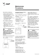
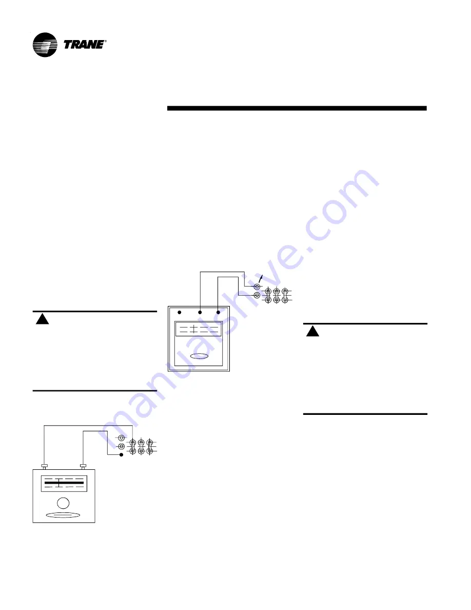
Fig. 10 - Indication for measuring
ohmic resistance
Fig. 11 - Indication of Megohmmeter
Measuring
The electric measurements above
should be done with the system's
general switch turned off.
Never use direct voltage on the
thermistor-type protector. This will
destroy it immediately.
Acceptable readings considered
safe to start up the compressor
should not be less than 1,000 ohms
per Volt of the motor's nominal
voltage.
Example:
Compressor of:
- 230 volts - 230,000 ohms
- 460 volts - 460,000 ohms
In general it is best to use a
megohmmeter of 500 Volts, DC
to test the insulation of the
compressor's motor coils. The use
of megohmmeters with a voltage
greater than 500 volts is not
recommendable for motors with
insulation less than 600 Volts
because, because they could damage
them.
Note: 1 megohm = 1,000,000 ohms.
The markings in general should be
within the range that goes from 1
megohm to infinite. If levels lower than
those above are found, the
compressor should be evacuated and
completely dehydrated and then break
the vacuum and elevate the pressure
to a positive level with refrigerant.
Clean the terminal plate. Then
measure again. If a low insulation
continues to be shown, a grounded
winding is recommended.
Voltage
Check the voltage at the compressor's
terminals while the system is working.
Checking the Insulation of the Motor
and Protection of the Coil
a. Use a megohmmeter of at least 500
V
- Measure insulation between phases
and casing
- Same between phases
b. Ohmic resistance
- Wheatstone bridge or precision
Ohmmeter (1.5 V)
- Thermistors: 90-750 ohms
- Thermostats: + - 1.0 ohm
CAUTION:
!
Never use a megohmmeter or apply
voltage to the motor coil when the
compressor is in vacuum. This could
damage the motor's coiling. Do not apply
the megohmmeter directly on the
terminals of the thermistor or
thermostat.
!
WARNING!
Because the motor acts as a
capacitor when the voltage is
applied, the motor terminals should
be grounded to the compressor's
casing during 60 seconds after the
test has been done. This will lower
the residual voltage in the motor that
could result in a severe electric
shock.
!
!
Summary of Contents for CGAD020
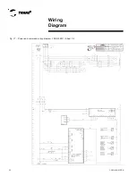
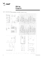
Page 36: ...CGAD SVN02C EN 36 Wiring Diagram Fig 17 Power and command wiring diagram CGAD 020C Sheet 1 2...
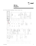
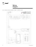
Page 52: ...CGAD SVN02C EN 52 Wiring Diagram Fig 33 Power and command wiring diagram CGAD 070C Sheet 1 2...
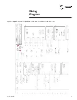
Page 60: ...CGAD SVN02C EN 60 Wiring Diagram Fig 41 Power and command wiring diagram CGAD100 Part I...
Page 61: ...CGAD SVN02C EN 61 Wiring Diagram Fig 42 Power and command wiring diagram CGAD100 Part II...
Page 62: ...CGAD SVN02C EN 62 Wiring Diagram Fig 43 Power and command wiring diagram CGAD100 Part III...
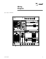
Page 63: ...CGAD SVN02C EN 63 Wiring Diagram Fig 44 Layout diagram CGAD100...
Page 64: ...CGAD SVN02C EN 64 Wiring Diagram Fig 45 Power and command wiring diagram CGAD120 Part I...
Page 65: ...CGAD SVN02C EN 65 Wiring Diagram Fig 46 Power and command wiring diagram CGAD120 Part II...
Page 66: ...CGAD SVN02C EN 66 Wiring Diagram Fig 47 Power and command wiring diagram CGAD 120 Part III...
Page 67: ...CGAD SVN02C EN 67 Wiring Diagram Fig 48 Layout diagram CGAD 120...
Page 68: ...CGAD SVN02C EN 68 Wiring Diagram Fig 49 Power and command wiring diagram CGAD150 Part I...
Page 69: ...CGAD SVN02C EN 69 Wiring Diagram Fig 50 Power and command wiring diagram CGAD150 Part II...
Page 70: ...CGAD SVN02C EN 70 Wiring Diagram Fig 51 Power and command wiring diagram CGAD150 Part III...
Page 71: ...CGAD SVN02C EN 71 Fig 52 Layout diagram CGAD150 Wiring Diagram...
Page 72: ...CGAD SVN02C EN 72 Wiring Diagram Fig 53 Layout diagram CGAD 100 125 150 with optionals...

