CGAD-SVN02C-EN
13
Application
Considerations
Water Treatment
Dirt, pebbles, corrosive products, and other
foreign matter will affect the heat transfer
between the water and the components of
the system. Foreign matter in the chilled
water system can also cause a pressure
drop and consequently reduce the flow of
water. Appropriate water treatment should
be determined at the location depending
on the type of system and local water
characteristics. It is not recommended to
use salt water in the CGAD liquid chillers
with air condensation. This would cause
the equipment's durability to decrease
considerably. Trane suggests using a
water treatment specialist familiarized with
the local water conditions to provide
consulting services for this decision and
establish an appropriate water treatment
program. The capacities given in the
section of performance data in this catalog
are based on water with an encrustation
factor of 0.00025. For capacities in other
encrustation factors, check with a Trane
engineer.
Effect of Altitude
on the Capacity
The capacity of the CGAD liquid chillers
with air condensation stated on the table of
performance data is considering
installation at sea level. In elevations
substantially above sea level, the lower air
density will lower the condenser's capacity
and therefore, the capacity and efficiency of
the entire unit. The adjustment factors for
table 2 may be applied directly to the
performance data of the catalog in order to
determine the unit's adjusted
performance.
Limitations of the Room
The CGAD liquid chillers with air
condensation offered by Trane were
designed for high durability under various
room conditions. The 20 to 150 TR liquid
chillers operate with temperatures
between 0
o
C to 45
o
C as standard. For
operation outside of these ranges, please
contact Trane's local sales office. The
minimum room temperatures are based
on soft breezes (not exceeding 8 km/h).
Higher wind speeds will result in a drop of
discharge pressure and therefore
increase the minimum ambient
temperature of operation and start.
Water Flow Limits
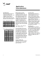
The minimum water flow rates are stated
on table 1 and a flow of the evaporator
below the levels on the table will result in a
drift causing problems of freezing,
encrustation, accumulation of impurities,
and temperature control problems. The
water flow of the evaporator is also given in
the section of general information. Flows
exceeding those listed may result in
excessive erosion of the tube. The
evaporator can resist a reduction of up to
50% of the water flow as long as this flow
is the same or greater than the minimal
requirements.
Temperature Limits
Variation of Leaving Water Temperature
The CGAD liquid chillers with air
condensation offered by Trane have three
distinct water output categories: standard,
low temperature, and ice making. The
standard variation of leaving water
temperature is 4 to 15
o
C. Machines of low
temperatures produce leaving water
temperatures between -18 and 4
o
C. Since
adjustment points of the water supply
temperature between -18 and 4
o
C result in
suction temperatures equal to or lower
than the water freezing point, a glycol
solution is needed for all the low-
temperature machines.
Ice making machines have a variation of
leaving water temperature between -7 and
15
o
C. Ice making controls include a
double adjustment point for controlling and
protecting the ice making capacity and
standard refrigeration. Check with Trane's
engineer assigned to your site for
applications or selections that have to do
with low temperature or ice making
machines (special order).
The maximum water temperature that can
be circulated through an evaporator while
the unit is on is 42
o
C. The evaporator
becomes limited due to the thermal stress
at this temperature.
Drop in Temperature
of the Entering Water
The performance data for Trane's CGAD
liquid chillers with air condensation are
based on a drop of chilled water
temperature of 5.5
o
C. Drops in
temperature outside of this variation will
result in a performance of the unit that
differs from those in the catalog. For
performance data outside of the variation of
5.5
o
C, check with a Trane engineer before
making your choice. Drops in chilled water
temperature from 3.3 to 10
o
C may be used
as long as the minimum and maximum
temperatures of water and minimum and
maximum flow rates are not violated.
Drops in temperature beyond 3.3 to 10
o
C
are not within the optimum variation for
control.
Furthermore, drops in temperature of less
than 3.3
o
C may result in inadequate
superheat of the refrigerant. Calibrated
superheat is always one of the first
concerns in any direct spread system and
it is especially important in liquid chiller
equipment where the evaporator is
connected to the compressor. When the
drop in temperature is less than 3.3
o
C, it
may be necessary to bypass part of the
entering water directly into the tubing of the
evaporator's leaving water.
Pressure from the side of Disarmament
Lower Pressure
The values of disarmament to the side of
low pressure adjusted at the factory are:
-- R407C: 25 psig.
Summary of Contents for CGAD020
Page 36: ...CGAD SVN02C EN 36 Wiring Diagram Fig 17 Power and command wiring diagram CGAD 020C Sheet 1 2...
Page 52: ...CGAD SVN02C EN 52 Wiring Diagram Fig 33 Power and command wiring diagram CGAD 070C Sheet 1 2...
Page 60: ...CGAD SVN02C EN 60 Wiring Diagram Fig 41 Power and command wiring diagram CGAD100 Part I...
Page 61: ...CGAD SVN02C EN 61 Wiring Diagram Fig 42 Power and command wiring diagram CGAD100 Part II...
Page 62: ...CGAD SVN02C EN 62 Wiring Diagram Fig 43 Power and command wiring diagram CGAD100 Part III...
Page 63: ...CGAD SVN02C EN 63 Wiring Diagram Fig 44 Layout diagram CGAD100...
Page 64: ...CGAD SVN02C EN 64 Wiring Diagram Fig 45 Power and command wiring diagram CGAD120 Part I...
Page 65: ...CGAD SVN02C EN 65 Wiring Diagram Fig 46 Power and command wiring diagram CGAD120 Part II...
Page 66: ...CGAD SVN02C EN 66 Wiring Diagram Fig 47 Power and command wiring diagram CGAD 120 Part III...
Page 67: ...CGAD SVN02C EN 67 Wiring Diagram Fig 48 Layout diagram CGAD 120...
Page 68: ...CGAD SVN02C EN 68 Wiring Diagram Fig 49 Power and command wiring diagram CGAD150 Part I...
Page 69: ...CGAD SVN02C EN 69 Wiring Diagram Fig 50 Power and command wiring diagram CGAD150 Part II...
Page 70: ...CGAD SVN02C EN 70 Wiring Diagram Fig 51 Power and command wiring diagram CGAD150 Part III...
Page 71: ...CGAD SVN02C EN 71 Fig 52 Layout diagram CGAD150 Wiring Diagram...
Page 72: ...CGAD SVN02C EN 72 Wiring Diagram Fig 53 Layout diagram CGAD 100 125 150 with optionals...


