CGAD-SVN02C-EN
78
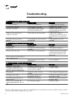
Troubleshooting
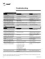
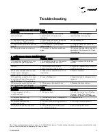
Note: These troubleshooting procedures apply to the CGAD Standard units. Troubleshooting with optional components should be checked
with the Technical Assistance Department at Trane do Brasil.
Symptoms
Possible Cause
Procedure
1. The voltmeter does not show a
supply of energy.
1. No electrical energy.
1. Check the power source.
2. The voltmeter does not show a
supply of energy to the contactors.
2. The disconnect is turned off.
2. Turn on the disconnect.
3. The voltmeter shows a voltage
before the fuses, but not after them.
3. Burnt fuse.
3. Change the fuses. Check the
motor's load.
4. The voltmeter shows a low
4. Low voltage.
4. Contact the Power Company.
5. Power is reaching the motor
terminals, but it does not start.
5. Motor is burnt.
5. Replace the motor.
6. Check the commands to see if the
coil of the contactor is not burnt.
6. Starter contactor does not close.
6. Fix it or change it.
7. The contactor does not receive
power.
7. The contact of the overload relay
is open.
7. Reset the overload relay.
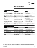
Symptoms
Possible Cause
Procedure
1. An electrical circuit test shows
that there is no power on the side of
the line with the motor's starting
1. No power.
1. Check the power source.
2. An electrical circuit test shows
that there is no power on the side of
the line with the motor's starting
2. Disconnect is open.
2. Determine why the switch was
open. If the system is in operational
conditions, turn on the switch.
3. An electrical circuit test shows
that there is power on the side of
the line but not on the fuse load
3. Burnt fuse.
3. Replace the fuse. Check the
motor's load.
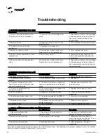
4. The voltmeter shows a low
voltage.
4. Low voltage.
4. Use a voltmeter to check and call
the Power Company.
5. Power is reaching the motor
terminals, but it does not start.
5. Motor is burnt.
5. Fix it or replace it.
6. Test to see if there are no burnt
coils or split contacts.
6. The starter switch is broken.
6. Fix it or replace it.
7. The coil of the motor's starting
switch does not receive energy.
7. Control circuit is open.
7. Locate which control turned off
and why.
7.1. High-pressure switch
7.2. Low-pressure switch
7.3. Pressure limit switch
7.4. Motor protector
7.5. Interlocking circuit is open.
7.6. Turned off by the ambient
8. The compressor does not work.
8. The compressor is jammed or
damaged.
8. Fix or replace the compressor.
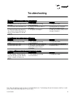
A . CONDENSER FAN DOES NOT START
B. COMPRESSOR DOES NOT START
Summary of Contents for CGAD020
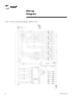
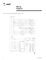
Page 36: ...CGAD SVN02C EN 36 Wiring Diagram Fig 17 Power and command wiring diagram CGAD 020C Sheet 1 2...
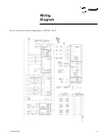
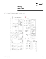
Page 52: ...CGAD SVN02C EN 52 Wiring Diagram Fig 33 Power and command wiring diagram CGAD 070C Sheet 1 2...
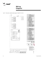
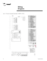
Page 60: ...CGAD SVN02C EN 60 Wiring Diagram Fig 41 Power and command wiring diagram CGAD100 Part I...
Page 61: ...CGAD SVN02C EN 61 Wiring Diagram Fig 42 Power and command wiring diagram CGAD100 Part II...
Page 62: ...CGAD SVN02C EN 62 Wiring Diagram Fig 43 Power and command wiring diagram CGAD100 Part III...
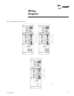
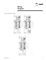
Page 63: ...CGAD SVN02C EN 63 Wiring Diagram Fig 44 Layout diagram CGAD100...
Page 64: ...CGAD SVN02C EN 64 Wiring Diagram Fig 45 Power and command wiring diagram CGAD120 Part I...
Page 65: ...CGAD SVN02C EN 65 Wiring Diagram Fig 46 Power and command wiring diagram CGAD120 Part II...
Page 66: ...CGAD SVN02C EN 66 Wiring Diagram Fig 47 Power and command wiring diagram CGAD 120 Part III...
Page 67: ...CGAD SVN02C EN 67 Wiring Diagram Fig 48 Layout diagram CGAD 120...
Page 68: ...CGAD SVN02C EN 68 Wiring Diagram Fig 49 Power and command wiring diagram CGAD150 Part I...
Page 69: ...CGAD SVN02C EN 69 Wiring Diagram Fig 50 Power and command wiring diagram CGAD150 Part II...
Page 70: ...CGAD SVN02C EN 70 Wiring Diagram Fig 51 Power and command wiring diagram CGAD150 Part III...
Page 71: ...CGAD SVN02C EN 71 Fig 52 Layout diagram CGAD150 Wiring Diagram...
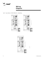
Page 72: ...CGAD SVN02C EN 72 Wiring Diagram Fig 53 Layout diagram CGAD 100 125 150 with optionals...

