CGAD-SVN02C-EN
17
refrigerant into the atmosphere.
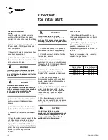
[ ] Fill out the "Start-up Sheet" that comes
with the equipment.
Once the unit is operating normally,
keep the machine house clean and the
tools in place. Make sure that the
doors of the control panels are in
place.
New regulationSuperheat of the
New regulation
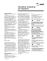
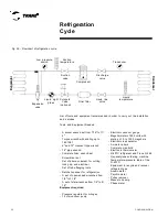
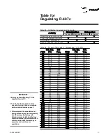
The normal superheat for each circuit is
5°C to 10°C at full charge. If the superheat
is not within this range, adjust the
calibration of the superheat of the
expansion valve. Allow 5 to 10 minutes
between the adjustments to give time for
the expansion valve to stabilize after each
new adjustment.
Sub-cooling System
The normal sub-cooling each circuit is 6 °
C to 12 ° C at full load. If the sub-cooling
isn’t in this range, check the circuit
overheating and adjust if necessary.
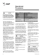
Operational Conditions
Once the unit has been operating for
approximately 10 minutes and the
system is stabilized, check the
operational conditions and complete
the following checklist of procedures:
[ ] Check once again the flow of water
and the drops of pressure through the
evaporator and the condenser. These
readings should be stable and at
appropriate levels. If the differential
pressure drops, clean all the water
supply filters.
[ ] Check the suction and discharge
pressures in the unit's pressure
gauges.
Pressures
Take a reading of the discharge
pressure at the connection of the
service valve seat. The suction
pressure levels at the Schrader valve
on the suction line should be as
follows:
Normal pressure levels
Pressures
Normal Values
Discharge
200 to 360 psig
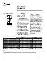
[ ] Check the oil level in the compressors.
At full charge, the oil level should be visible
at the compressor's oil sight glass. If not,
add or remove oil as needed. See table 04
for a list of the types of oil recommended
and the correct amounts for the units.
[ ] Check and record the amperage
consumed by the compressor. Compare
the readings with the compressor's
electrical information shown on its plate.
[ ] Check the liquid sight glass. The flow of
refrigerant should be clean. Bubbles in the
liquid indicate a low charge of refrigerant or
excessive loss of pressure on the liquid
line.
A restriction can frequently be identified by
a notable difference in temperature
between one side and another of the
restricted area. Frequently ice forms at the
outlet of the liquid line at this point too.
Check table XX in this manual.
[ ] Once the oil level, the amperage,
and the operational pressures are
stabilized, measure the superheat.
Read the section on superheat and
subcooling in this manual.
[ ] Measure the subcooling. Read the
section on superheat and subcooling
in this manual.
[ ] If the operational pressure, liquid
sight glass, the superheat, and the
subcooling indicate a lack of
refrigerant gas, add gas to each
circuit. The lack of refrigerant is
indicated if the work pressures are low
and the subcooling is also low.
[ ] Add refrigerant gas (only in the gas
form) with the unit in operation by
adding a gas charge at the Schrader
valve situated on the suction line until
the operational conditions have
normalized.
[ ] If the operational conditions indicate an
overcharge of gas, then slowly remove
refrigerant through the service valve
located on the liquid line. Do not discharge
Operational
Conditions
WARNING!
!
CAUTION:
!
In order to minimize the use of the
pressure gauges, close the valves in
order to isolate them after their use.
CAUTION:
!
The system may not have the right
charge of refrigerant even though the
liquid sight glass is clean. Superheat,
subcooling, and operational pressures
must also be taken into consideration.
CAUTION:
!
If the suction and discharge pressures
are low but the subcooling is normal,
there is no lack of refrigerant gas. To add
gas would result in overcharge.
CAUTION:
!
In order to avoid damaging the compres-
sor and ensure full cooling capacity, only
use the refrigerant that is specified on
the equipment's identification plate.
CAUTION:
!
In order to avoid damaging the
compressors, do not allow the
refrigerant liquid to get into the suction
line.
In order to avoid injuries from freezing, do
not have direct contact with the
refrigerant.
Summary of Contents for CGAD020
Page 36: ...CGAD SVN02C EN 36 Wiring Diagram Fig 17 Power and command wiring diagram CGAD 020C Sheet 1 2...
Page 52: ...CGAD SVN02C EN 52 Wiring Diagram Fig 33 Power and command wiring diagram CGAD 070C Sheet 1 2...
Page 60: ...CGAD SVN02C EN 60 Wiring Diagram Fig 41 Power and command wiring diagram CGAD100 Part I...
Page 61: ...CGAD SVN02C EN 61 Wiring Diagram Fig 42 Power and command wiring diagram CGAD100 Part II...
Page 62: ...CGAD SVN02C EN 62 Wiring Diagram Fig 43 Power and command wiring diagram CGAD100 Part III...
Page 63: ...CGAD SVN02C EN 63 Wiring Diagram Fig 44 Layout diagram CGAD100...
Page 64: ...CGAD SVN02C EN 64 Wiring Diagram Fig 45 Power and command wiring diagram CGAD120 Part I...
Page 65: ...CGAD SVN02C EN 65 Wiring Diagram Fig 46 Power and command wiring diagram CGAD120 Part II...
Page 66: ...CGAD SVN02C EN 66 Wiring Diagram Fig 47 Power and command wiring diagram CGAD 120 Part III...
Page 67: ...CGAD SVN02C EN 67 Wiring Diagram Fig 48 Layout diagram CGAD 120...
Page 68: ...CGAD SVN02C EN 68 Wiring Diagram Fig 49 Power and command wiring diagram CGAD150 Part I...
Page 69: ...CGAD SVN02C EN 69 Wiring Diagram Fig 50 Power and command wiring diagram CGAD150 Part II...
Page 70: ...CGAD SVN02C EN 70 Wiring Diagram Fig 51 Power and command wiring diagram CGAD150 Part III...
Page 71: ...CGAD SVN02C EN 71 Fig 52 Layout diagram CGAD150 Wiring Diagram...
Page 72: ...CGAD SVN02C EN 72 Wiring Diagram Fig 53 Layout diagram CGAD 100 125 150 with optionals...

