CGAD-SVN02C-EN
32
Screens
Function Keys
With this touch screen application, the
function keys are completely determined
by the software and change depending on
the topic presented at the moment. The
functions of the touch screen are listed
below:
Radio Buttons
The radio buttons show an option from the
menu between two or more alternatives
and all of them are visible. This is the
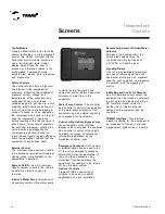
START-UP (AUTO) button in figure 13.
The model of the radio button imitates the
buttons used by the old radios to select a
station. When a button is pressed, the one
that had been pressed previously shows
and the new station is selected. In the
DynaView model, each possible selection
is associated to a button.
The button selected darkens and is
highlighted to indicate which option is
selected. All the set of possible options is
always visible along with the current
option.
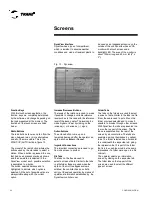
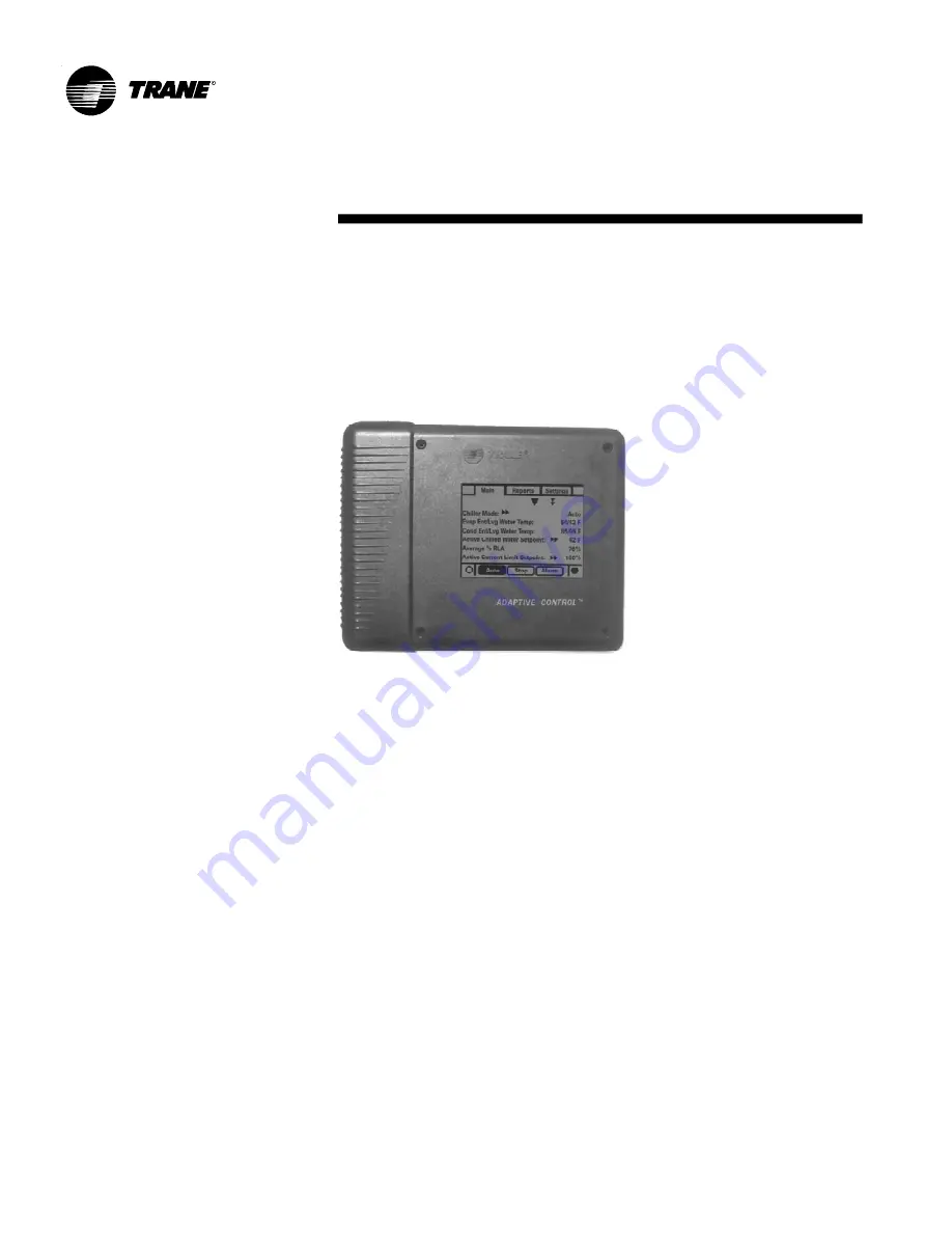
Fig. 13 - Dynaview
DynaView Interface
DynaView has a type of compartment,
which is resistant to adverse weather
conditions and made of resistant plastic to
be used as an independent device on the
outside of the unit. DynaView has a VGA
monitor with a touch screen and a
backlight LED. The area of the monitor is
about 102mm long and 60 mm tall (4" x
3").
Increase/Decrease Buttons
The levels of the rotation are used to make
it possible to change a variable reference
level such as is the case with the reference
level of the leaving water. The level can be
made higher or lower by clicking on the
increase (+) or decrease ( - ) signs.
Action buttons
The actions button come up on a
temporary basis and offer the operator an
option, such as
Enter
or
Cancel
.
Important Connections
The important connections are used to go
from one screen to another.
File Tabs
The tabs on the files are used to
select a screen of data. Similar to the tabs
in a file folder, these are used when the
option of the Hot Gas Bypass valve is
solicited, the controller has an outlet to
carry out the valve's operation by means of
operational information established by the
DynaView controller user.
Folder Tabs
The tabs on the folders are used to select
a screen of data. Similar to the tabs in a file
folder, these are used to put a title on the
folder or screen selected and to make it
possible to browse through other screens.
With DynaView, the tabs are presented in a
row on the top part of the screen. The file
tabs are separated from the rest of the
screen by a horizontal line. The tabs are
separated among themselves by vertical
lines. The folder selected has a horizontal
line underneath the respective tab, giving
the impression that it is part of the folder
that is to be used (as would be the same
impressions if a folder were open in a file
cabinet).
The operator selects an information
screen by clicking on the respective tab.
The folder tabs on the top part of the
screen are used to select the different
types of screen.
Summary of Contents for CGAD020
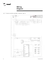
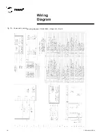
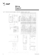
Page 36: ...CGAD SVN02C EN 36 Wiring Diagram Fig 17 Power and command wiring diagram CGAD 020C Sheet 1 2...
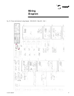
Page 52: ...CGAD SVN02C EN 52 Wiring Diagram Fig 33 Power and command wiring diagram CGAD 070C Sheet 1 2...
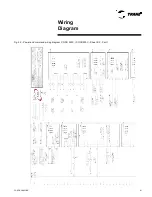
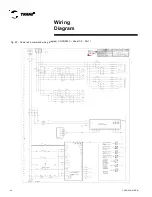
Page 60: ...CGAD SVN02C EN 60 Wiring Diagram Fig 41 Power and command wiring diagram CGAD100 Part I...
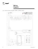
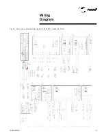
Page 61: ...CGAD SVN02C EN 61 Wiring Diagram Fig 42 Power and command wiring diagram CGAD100 Part II...
Page 62: ...CGAD SVN02C EN 62 Wiring Diagram Fig 43 Power and command wiring diagram CGAD100 Part III...
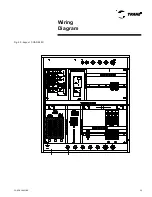
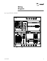
Page 63: ...CGAD SVN02C EN 63 Wiring Diagram Fig 44 Layout diagram CGAD100...
Page 64: ...CGAD SVN02C EN 64 Wiring Diagram Fig 45 Power and command wiring diagram CGAD120 Part I...
Page 65: ...CGAD SVN02C EN 65 Wiring Diagram Fig 46 Power and command wiring diagram CGAD120 Part II...
Page 66: ...CGAD SVN02C EN 66 Wiring Diagram Fig 47 Power and command wiring diagram CGAD 120 Part III...
Page 67: ...CGAD SVN02C EN 67 Wiring Diagram Fig 48 Layout diagram CGAD 120...
Page 68: ...CGAD SVN02C EN 68 Wiring Diagram Fig 49 Power and command wiring diagram CGAD150 Part I...
Page 69: ...CGAD SVN02C EN 69 Wiring Diagram Fig 50 Power and command wiring diagram CGAD150 Part II...
Page 70: ...CGAD SVN02C EN 70 Wiring Diagram Fig 51 Power and command wiring diagram CGAD150 Part III...
Page 71: ...CGAD SVN02C EN 71 Fig 52 Layout diagram CGAD150 Wiring Diagram...
Page 72: ...CGAD SVN02C EN 72 Wiring Diagram Fig 53 Layout diagram CGAD 100 125 150 with optionals...

