CGAD-SVN02C-EN
79
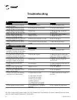
Troubleshooting
Note: These troubleshooting procedures apply to the CGAD Standard units. Troubleshooting with optional components should be checked
with the Technical Assistance Department at Trane do Brasil.
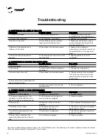
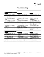
Sympt oms
P ossibl e C ause
P roc edure
9. Contacts of the low-pressure
switch are open.
9. Suction pressure is below the
control point of the pressure
regulator.
9. Check for loss of refrigerant,
repair the leak, and recharge.
10. Contacts of the high-pressure
switch are open. High pressure is
10. Discharge pressure is above the
high-pressure control point.
10. See problem G.
11. The starter switch does not stay
closed.
11. The contacts of the overload
relay are open.
11. Reset the relay, the RCM, and
check the cause.
12. The system does not start up.
12. Contacts of the flow switch are
open.
12. Restore the water flow, check the
operation of the flow switch. Check
the switches.
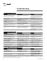
Sympt oms
P ossibl e C ause
P roc edure
1. Operation is normal, but it stops
and starts with great frequency.
1. Intermittent contact in the control
circuit (bad electrical contact).
1. Repair or replace the defective
control.
2. Same.
2. The differential of the low-
pressure switch is too narrow.
2. Adjust the differential for normal
working conditions.
3. The valve squeaks when closed.
There is also a change in
temperature on the refrigerant line
3. Leak on the solenoid valve of the
liquid line.
3. Repair or replace.
4. Operation is normal, but it stops
and starts with great frequency by
the PB. Bubbles in the sight glass.
4. Lack of refrigerant.
4. Repair the leak of refrigerant and
recharge.
5. Suction pressure is too low and
ice is being formed on the dryer.
5. The dryer on the liquid line is
plugged.
5. Replace the dryer nucleus.
C . C OMP RESSOR WORK S INTERMI TTENTLY
B. C OMP RESSOR D OES NOT STA RT (C ont .)
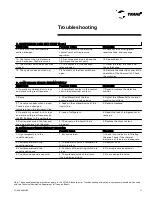
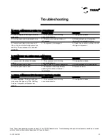
Symptoms
Possible Cause
Procedure
1. High temperature in the
conditioned area.
1. Excessive load.
1. Check if outside air is infiltrating
the area. Check if the thermal
insulation of the area is inadequate.
2. Low temperature in the
conditioned area.
2. Thermostat is set to a temperature
that is too low.
2. Readjust or fix.
3. Low temperature in the
conditioned space.
3. Contacts of the starting switch are
stuck.
3. Fix or replace the contactor.
4. Conditioned space is too cold.
4. The solenoid valve of the liquid
line is open and stuck.
4. Fix or change the valve.
D. COMPRESSOR WORKS WITHOUT STOPPING
Summary of Contents for CGAD020
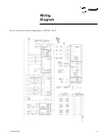
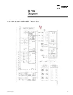
Page 36: ...CGAD SVN02C EN 36 Wiring Diagram Fig 17 Power and command wiring diagram CGAD 020C Sheet 1 2...
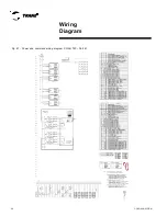
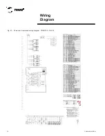
Page 52: ...CGAD SVN02C EN 52 Wiring Diagram Fig 33 Power and command wiring diagram CGAD 070C Sheet 1 2...
Page 60: ...CGAD SVN02C EN 60 Wiring Diagram Fig 41 Power and command wiring diagram CGAD100 Part I...
Page 61: ...CGAD SVN02C EN 61 Wiring Diagram Fig 42 Power and command wiring diagram CGAD100 Part II...
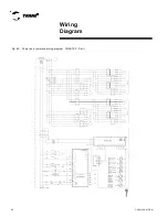
Page 62: ...CGAD SVN02C EN 62 Wiring Diagram Fig 43 Power and command wiring diagram CGAD100 Part III...
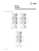
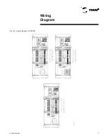
Page 63: ...CGAD SVN02C EN 63 Wiring Diagram Fig 44 Layout diagram CGAD100...
Page 64: ...CGAD SVN02C EN 64 Wiring Diagram Fig 45 Power and command wiring diagram CGAD120 Part I...
Page 65: ...CGAD SVN02C EN 65 Wiring Diagram Fig 46 Power and command wiring diagram CGAD120 Part II...
Page 66: ...CGAD SVN02C EN 66 Wiring Diagram Fig 47 Power and command wiring diagram CGAD 120 Part III...
Page 67: ...CGAD SVN02C EN 67 Wiring Diagram Fig 48 Layout diagram CGAD 120...
Page 68: ...CGAD SVN02C EN 68 Wiring Diagram Fig 49 Power and command wiring diagram CGAD150 Part I...
Page 69: ...CGAD SVN02C EN 69 Wiring Diagram Fig 50 Power and command wiring diagram CGAD150 Part II...
Page 70: ...CGAD SVN02C EN 70 Wiring Diagram Fig 51 Power and command wiring diagram CGAD150 Part III...
Page 71: ...CGAD SVN02C EN 71 Fig 52 Layout diagram CGAD150 Wiring Diagram...
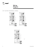
Page 72: ...CGAD SVN02C EN 72 Wiring Diagram Fig 53 Layout diagram CGAD 100 125 150 with optionals...

