CGAD-SVN02C-EN
75
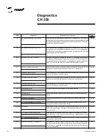
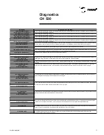
T yp e
R eset
Excessive Loss of Comm
Comm Loss: External Auto/Stop
Comm Loss: Emergency Stop
Comm Loss: Ext Ice Building Ctrl Input
Comm Loss: Outdoor Air Temperature
Comm Loss: Evap Leaving Water Temp
Comm Loss: Evap Entering Water Temp
Comm Loss: Condenser Leaving Water Temp
Comm Loss: Condenser Entering Water Temp
Comm Loss: Discharge Pressure Transducer
Comm Loss: Suction Pressure Transducer
Comm Loss: External Chilled Water Setpoint
Comm Loss: High Pressure Cutout Switch
Comm Loss: Evaporator Water Flow Switch
Comm Loss: Condenser Water Flow Switch
Comm Loss: Evaporator Water Pump Relay
Comm Loss: Condenser Water Pump Relay
Comm Loss: Local BAS Interface
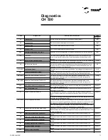
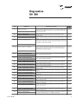
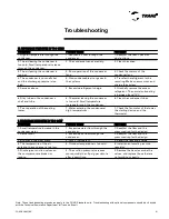
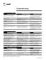
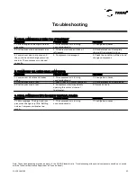
5F9
A loss of communication was detected between the controller and the module of the
condenser water pump relay.
Remote
69D
A loss of communication was detected between the controller and the communication
module that connects the equipment to the managing system (BAS)
Remote
6B6
A loss of communication was detected between the controller and the module of the
condenser water flow switch.
Remote
5F8
A loss of communication was detected between the controller and the module of the
evaporator water pump relay.
Remote
5EB
A loss of communication was detected between the controller and the high pressure
cutout switch.
Remote
5EF
A loss of communication was detected between the controller and the module of the
evaporator water flow switch.
Remote
6B6
A loss of communication was detected between the controller and the suction pressure
transducer.
Remote
5,00E+09
A loss of communication was detected between the controller and the external chilled
water setpoint.
Remote
6B6
A loss of communication was detected between the controller and the temperature
sensor of the water entering the condenser.
Remote
6B6
A loss of communication was detected between the controller and the discharge
pressure transducer.
Remote
5,00E+04
A loss of communication was detected between the controller and the temperature
sensor of the water entering the evaporator.
Remote
6B6
A loss of communication was detected between the controller and the temperature
sensor of the water leaving the condenser.
Remote
5,00E+02
A loss of communication was detected between the controller and the outdoor air
temperature sensor. This will put in operation all of the condenser's fans when the
equipment has an air condensation system.
Remote
5,00E+03
A loss of communication was detected between the controller and the temperature
sensor of the water leaving the evaporator.
Remote
5DE
A loss of communication was detected between the controller and the Emergency Stop
module.
Remote
5,00E+01
A loss of communication was detected between the controller and the Comm Loss: Ice
Building module. The equipment is placed in a normal mode of operation. Ice building is
not permitted until the problem is corrected.
Remote
5C4
A loss of communication was detected with more than 20%of the modules and sensors
installed. Check the voltage on the modules or poor contact on the connecting cable of
the modules/sensors (LLID).
Remote
5DD
A loss of communication was detected between the controller and the External
Auto/Stop module.
Remote
C od e
D iagno st ic
D escrip t io n o f Pr ob lem
Diagnostics
CH 530
Summary of Contents for CGAD020
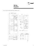
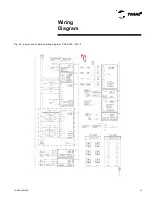
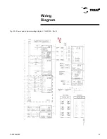
Page 36: ...CGAD SVN02C EN 36 Wiring Diagram Fig 17 Power and command wiring diagram CGAD 020C Sheet 1 2...
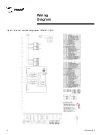
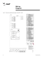
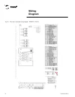
Page 52: ...CGAD SVN02C EN 52 Wiring Diagram Fig 33 Power and command wiring diagram CGAD 070C Sheet 1 2...
Page 60: ...CGAD SVN02C EN 60 Wiring Diagram Fig 41 Power and command wiring diagram CGAD100 Part I...
Page 61: ...CGAD SVN02C EN 61 Wiring Diagram Fig 42 Power and command wiring diagram CGAD100 Part II...
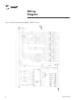
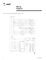
Page 62: ...CGAD SVN02C EN 62 Wiring Diagram Fig 43 Power and command wiring diagram CGAD100 Part III...
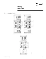
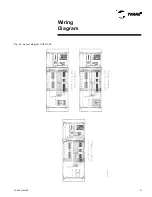
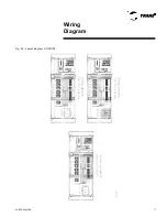
Page 63: ...CGAD SVN02C EN 63 Wiring Diagram Fig 44 Layout diagram CGAD100...
Page 64: ...CGAD SVN02C EN 64 Wiring Diagram Fig 45 Power and command wiring diagram CGAD120 Part I...
Page 65: ...CGAD SVN02C EN 65 Wiring Diagram Fig 46 Power and command wiring diagram CGAD120 Part II...
Page 66: ...CGAD SVN02C EN 66 Wiring Diagram Fig 47 Power and command wiring diagram CGAD 120 Part III...
Page 67: ...CGAD SVN02C EN 67 Wiring Diagram Fig 48 Layout diagram CGAD 120...
Page 68: ...CGAD SVN02C EN 68 Wiring Diagram Fig 49 Power and command wiring diagram CGAD150 Part I...
Page 69: ...CGAD SVN02C EN 69 Wiring Diagram Fig 50 Power and command wiring diagram CGAD150 Part II...
Page 70: ...CGAD SVN02C EN 70 Wiring Diagram Fig 51 Power and command wiring diagram CGAD150 Part III...
Page 71: ...CGAD SVN02C EN 71 Fig 52 Layout diagram CGAD150 Wiring Diagram...
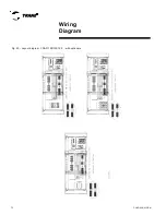
Page 72: ...CGAD SVN02C EN 72 Wiring Diagram Fig 53 Layout diagram CGAD 100 125 150 with optionals...

