CGAD-SVN02C-EN
25
!
WARNING!
In order to prevent accidents or
injuries from electric shocks, turn off
and lock in place all the electric
disconnects.
adding refrigerant.
RECLAIMINGREFRIGERANTFOR
SERVICE
The CGAD units 020, 025, and 030 have
only one circuit. The CGAD units 040,
045, and 050 have two circuits.
a. If the equipment is operating, turn the
A1 switch to the OFF position and
allow the compressors to reclaim the
gas normally. If the equipment is off,
do step B.
b. Turn off the power disconnect and
adjust the RCM leaving water setpoint
low enough to ensure that it calls for
cooling when the equipment turns on.
c. Install a jumper on terminals 117 and
118 of the low-pressure regulator of
circuit 1 (or on terminals 217 and 218
of circuit 2).
d. Turn on the power disconnect and
circuit breakers DJ3, DJ4, DJ5, DJ6.
e. Turn the Chiller switch to the ON
position. The lead compressor will
start up after the other. Allow both
circuits to operate for a period of at
least 5 minutes.
Carefully observe the suction
pressure of each circuit. The suction
pressure of any of the circuits could
drop below 10 psig during this period
of time. Immediately remove the
jumper or turn off the disconnect. If
this occurs, there is a malfunctioning
in the circuit. This problem should be
detected previously. If the unit
operates normally, continue on to step
F.
f. Manually close the service valve of the
liquid line in order to do the
reclaiming.
g. Carefully observe the suction
pressure manometer. When the
pressure drops to 10 psig, remove the
jumper from terminals 117-118 (or
217-218 in circuit 2).
It should also stop by the low-
pressure limit regulator. The com-
pressor should stop and in the sight
glass of the RCM should show bPA/
bPB, low pressure of refrigerant in
circuit A or B. Warning: do not operate
the scroll compressor in vacuum.
These compressors pull internally a
low vacuum if the suction side is
closed or restricted. This can cause
the aluminum rotor to bend, open the
circuit breaker, turn off the high
temperature thermostat, or burn the
fuses.
h. Manually close (seat) the discharge
service valve for this circuit.
i. Do the reclaiming from the other
circuit. Manually close the service
valve of the liquid line.
j. Carefully observe the suction pres-
sure manometer. When the pressure
drops to 10 psig, remove the jumper
from low-pressure switch 117-118
(Circuit 1) or 217-218 (Circuit 2).
CAUTION: The low-pressure limit
regulator should never be jumped.
The compressor should stop and in
the sight glass of the RCM should
show bPA/bPB, low pressure of
refrigerant in circuit A or B.
k. Close (seat) the discharge service
valve for this circuit.
l. Once the two circuits with the refriger-
ant are reclaimed, open and lock all
the disconnects. Keep the circuit
breakers open (OFF), which will keep
an accidental operation from happen-
ing while the circuit is without gas.
Operational
Procedures
Summary of Contents for CGAD020
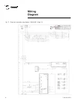
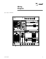
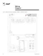
Page 36: ...CGAD SVN02C EN 36 Wiring Diagram Fig 17 Power and command wiring diagram CGAD 020C Sheet 1 2...
Page 52: ...CGAD SVN02C EN 52 Wiring Diagram Fig 33 Power and command wiring diagram CGAD 070C Sheet 1 2...
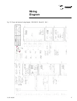
Page 60: ...CGAD SVN02C EN 60 Wiring Diagram Fig 41 Power and command wiring diagram CGAD100 Part I...
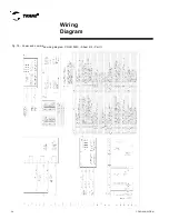
Page 61: ...CGAD SVN02C EN 61 Wiring Diagram Fig 42 Power and command wiring diagram CGAD100 Part II...
Page 62: ...CGAD SVN02C EN 62 Wiring Diagram Fig 43 Power and command wiring diagram CGAD100 Part III...
Page 63: ...CGAD SVN02C EN 63 Wiring Diagram Fig 44 Layout diagram CGAD100...
Page 64: ...CGAD SVN02C EN 64 Wiring Diagram Fig 45 Power and command wiring diagram CGAD120 Part I...
Page 65: ...CGAD SVN02C EN 65 Wiring Diagram Fig 46 Power and command wiring diagram CGAD120 Part II...
Page 66: ...CGAD SVN02C EN 66 Wiring Diagram Fig 47 Power and command wiring diagram CGAD 120 Part III...
Page 67: ...CGAD SVN02C EN 67 Wiring Diagram Fig 48 Layout diagram CGAD 120...
Page 68: ...CGAD SVN02C EN 68 Wiring Diagram Fig 49 Power and command wiring diagram CGAD150 Part I...
Page 69: ...CGAD SVN02C EN 69 Wiring Diagram Fig 50 Power and command wiring diagram CGAD150 Part II...
Page 70: ...CGAD SVN02C EN 70 Wiring Diagram Fig 51 Power and command wiring diagram CGAD150 Part III...
Page 71: ...CGAD SVN02C EN 71 Fig 52 Layout diagram CGAD150 Wiring Diagram...
Page 72: ...CGAD SVN02C EN 72 Wiring Diagram Fig 53 Layout diagram CGAD 100 125 150 with optionals...

