CGAD-SVN02C-EN
24
Operational
Procedures
Low Side Repairs
If the dryer, the solenoid valve, the
expansion valve, or the tubing on the low
side need repairing:
- Reclaim the refrigerant from the system.
- Allow the temperature of the components
to stabilize. This keeps the humidity from
condensing on the internal surfaces of the
system when open.
- When a new part is being installed, do
this in the shortest time possible, opening
the valve of the liquid line for an instant to
bleed the air. When the air has been bled,
immediately close the circuit.
- Remember that this method only applies
for small, short repairs. If a larger and
longer repair needs to be done, such as
opening the chiller or the compressor, it is
best that the entire low side of the system
be evacuated.
High Side Repairs
If the condenser, compressor, or tubing on
the high side need repairing, remove the
system's refrigerant charge. After repairs
are complete, make sure there are no
leaks.
Checking for Leaks
Use refrigerant as an element for detecting
leaks and dry nitrogen to reach the testing
pressure.
Test the high and low sides of the system
for the pressures stated by the local code.
If the testing pressure on the high side is
equal or greater to the calibrating of the
safety valve, remove the valve and install a
plug in the valve's mounting.
Under absolutely no circumstances
should oxygen or acetylene be used
instead of dry nitrogen - a violent
explosion could occur.
WARNING!
!
SYSTEM EVACUATION
The equipment needed to do the
complete evacuation is the following:
- A high-vacuum pump capable of
producing a vacuum equivalent to
500 microns.
- An electronic vacuum gauge
- Dry nitrogen
a. Connect the electronic vacuum gauge
to the suction pressure gauge or to
the connection on the tubing at the
entrance of the vacuum pump.
b. Close the access valves on the
pressure gauges at the instrument
panel so that they don't get damaged.
c. Connect the vacuum pump to the
liquid line connection valve and to the
suction valve. Open the valve that
connects the pump to the system.
d. Turn on the pump and evacuate the
system to 2.5 mm of mercury.
e. Break the vacuum using the Schrader
valve situated between the expansion
valve and the evaporator with dry
nitrogen and then evacuate again to
500 microns of mercury. Make the
connection before beginning the
vacuum.
f. Allow the system to remain in the
vacuum overnight or at least during 8
hours. If no noticeable increase
occurred during this time, remove the
equipment from evacuation.
g. Break the vacuum with R-407C and
open the access valves on the
pressure gauges at the instrument
panel.
Note: Use a Double-State High Vacuum
pump and Measuring Gauge that are
capable of reaching the minimum of 500
microns.
a. Connect the refrigerant cylinder to the
liquid line connection valve. Increase
the system's high side pressure to 0.8
- 1 kgf/cm2 (12 - 15 psig).
b. Completely close (to the cylinder) the
liquid line valve and remove the
refrigerant connection.
c. Increase the system's pressure to the
level needed using dry nitrogen.
d. Test the system's high side for leaks
and then lower the testing pressure.
If leaks are seen, they must be
repaired and the system tested
again.
e. For the system's low side, connect
the pressure with the service angle
valve on the suction line.
f. Use refrigerant as the detecting
element and dry nitrogen to develop
the testing pressure of
7 kgf/cm
2
(100 psig). Always use a
pressure regulator.
g. Test this side of the system making
sure there are no leaks and then
lower the testing pressure. If leaks
are found, repair them and then test
the low side.
Summary of Contents for CGAD020
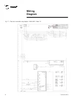
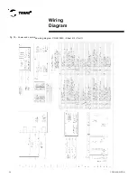
Page 36: ...CGAD SVN02C EN 36 Wiring Diagram Fig 17 Power and command wiring diagram CGAD 020C Sheet 1 2...
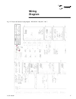
Page 52: ...CGAD SVN02C EN 52 Wiring Diagram Fig 33 Power and command wiring diagram CGAD 070C Sheet 1 2...
Page 60: ...CGAD SVN02C EN 60 Wiring Diagram Fig 41 Power and command wiring diagram CGAD100 Part I...
Page 61: ...CGAD SVN02C EN 61 Wiring Diagram Fig 42 Power and command wiring diagram CGAD100 Part II...
Page 62: ...CGAD SVN02C EN 62 Wiring Diagram Fig 43 Power and command wiring diagram CGAD100 Part III...
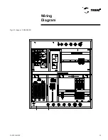
Page 63: ...CGAD SVN02C EN 63 Wiring Diagram Fig 44 Layout diagram CGAD100...
Page 64: ...CGAD SVN02C EN 64 Wiring Diagram Fig 45 Power and command wiring diagram CGAD120 Part I...
Page 65: ...CGAD SVN02C EN 65 Wiring Diagram Fig 46 Power and command wiring diagram CGAD120 Part II...
Page 66: ...CGAD SVN02C EN 66 Wiring Diagram Fig 47 Power and command wiring diagram CGAD 120 Part III...
Page 67: ...CGAD SVN02C EN 67 Wiring Diagram Fig 48 Layout diagram CGAD 120...
Page 68: ...CGAD SVN02C EN 68 Wiring Diagram Fig 49 Power and command wiring diagram CGAD150 Part I...
Page 69: ...CGAD SVN02C EN 69 Wiring Diagram Fig 50 Power and command wiring diagram CGAD150 Part II...
Page 70: ...CGAD SVN02C EN 70 Wiring Diagram Fig 51 Power and command wiring diagram CGAD150 Part III...
Page 71: ...CGAD SVN02C EN 71 Fig 52 Layout diagram CGAD150 Wiring Diagram...
Page 72: ...CGAD SVN02C EN 72 Wiring Diagram Fig 53 Layout diagram CGAD 100 125 150 with optionals...

