background image

BRAKES

8-53

TX525 Service Manual 

Rev. 000

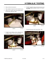
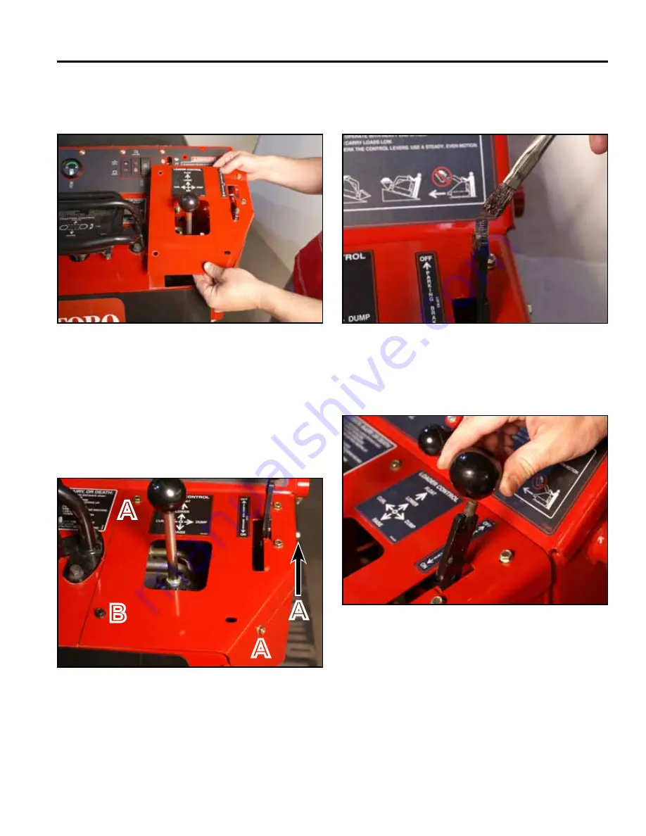
8.  Position the right panel onto the control panel 

assembly (Fig. 1832).

10. Apply thread locking compound (Loctite 416 or 

equivalent) to brake handle threads (Fig. 1834).

A.  Self-tapping screw (3) 

B.  Bolt and nut


Fig 1832


PICT-4343a


Fig 1834


PICT-5526

11.  Install the knob onto the brake handle (Fig. 1835).

9.  Using a 3/8” socket, install 3 self-tapping screws 

securing the top right panel to the control panel 

assembly. Using a 3/8” socket and a 7/16” socket, 

install the bolt and nut securing the lower left corner 

of the top right panel to the control panel assembly 

(Fig. 1833).


Fig 1835


PICT-4342


Fig 1833


PICT-4341

A

B

A

A

Summary of Contents for Dingo TX 525

Page 1: ...TX525 Service Manual Sitework Systems Form No 492 9195...

Page 2: ...epair instructions Units covered on in this manual are TX525 Wide and Narrow Track model years 2007 current The manual may also be specified for use on later model products The hydraulic power system...

Page 3: ...ii Rev 000 TX525 Service Manual 8 01 10 Revision 000 REVISIONS...

Page 4: ...0 MAINTENANCE Recommended Maintenance Schedule 3 1 Greasing the Traction Unit 3 2 Maintaining the Road Wheels 3 3 Hydraulic Reservoir Tank 3 4 Location 3 4 Checking the Hydraulic Fluid 3 4 Replacing t...

Page 5: ...Cooling Fan Replacement 4 37 Cooling Fan Removal 4 37 Cooling Fan Installation 4 38 Flywheel Replacement 4 40 Flywheel Removal 4 40 Flywheel Installation 4 44 Starter Replacement 4 49 Starter Removal...

Page 6: ...4 How It Works 5 4 Testing 5 4 Relay 5 5 Purpose 5 5 Location 5 5 How It Works 5 5 Testing 5 6 Engine Oil Pressure and Battery Charge Indicator Light Cluster 5 6 Purpose 5 6 Location 5 6 How It Works...

Page 7: ...Low Engine Oil 5 13 Purpose 5 13 Location 5 13 How It Works 5 13 Testing 5 13 Fuses 5 14 Purpose 5 14 Location 5 14 How It Works 5 14 Testing 5 14 Fusible Link 5 14 Purpose 5 14 Location 5 14 How It...

Page 8: ...bly 6 45 14 gpm Pump Assembly 6 48 6 gpm Pump Assembly 6 51 Hydraulic Tandem Pump Assembly 6 54 Auxiliary Valve Rebuild 6 57 Auxiliary Valve 6 57 Relief Assembly 6 64 Spool Assembly 6 64 Auxiliary Val...

Page 9: ...Wide Track 7 90 Tensioner Arm Wheel Bearing Removal Wide Track 7 90 Tensioner Arm Wheel Bearing Installation Wide Track 7 94 Tensioner Wheel Bearing Replacement Narrow Track 7 97 Tensioner Wheel Beari...

Page 10: ...3 Auxiliary Circuit Pressure Test 9 4 Removal of Pressure Gauge 9 5 Auxiliary Circuit Flow Test 9 7 Auxiliary Flow Testing 9 7 Troubleshooting 9 7 Flow Meter Removal 9 7 Loader Circuit Flow Testing 9...

Page 11: ...x Rev 000 TX525 Service Manual TABLE OF CONTENTS THIS PAGE INTENTIONALLY LEFT BLANK...

Page 12: ...tment 8111 Lyndale Avenue South Bloomington MN 55420 SAFETY INFORMATION General Information Think Safety First SAFETY INFORMATION 1 General Information This symbol means WARNING or PERSONAL SAFETY INS...

Page 13: ...e hydraulic fluid Use cardboard or paper to find hydraulic leaks Hydraulic fluid escaping under pressure can penetrate the skin and cause injury Fluid accidentally injected into the skin must be surgi...

Page 14: ...63 liters with filter Fuel Tank 6 gallons 22 7 liters TX525 Narrow Track TX525 Wide Track Overall Length without Bucket 70 7 179 6cm 70 7 179 6cm Overall Length with Bucket 92 233 7cm 92 233 7cm Overa...

Page 15: ...f water and ethylene glycol 8 hours clean radiator 100 hours check cooling system hoses yearly change engine coolant More often in dusty dirty conditions Performance Narrow Track Item Specification Ti...

Page 16: ...ven off of the auxiliary drive shaft on the front of the engine The circuit charge pressure is supplied by a 5 psi 34 bar check valve in the loader pump return circuit The pumps have service bypass va...

Page 17: ...acity 10 5 gallons 39 7 liters Filter In addition to the in tank screens the loader circuit passes through a 10 micron spin on filter prior to returning to tank Item Specification Track The tracks are...

Page 18: ...revailing torque feature hardness of the surface underneath of the fastener s head or similar condition which affects the installation As noted in the following tables torque values should be reduced...

Page 19: ...ht Nuts SAE J995 Grade 2 or Stronger Nuts In lb In lb N cm In lb N cm In lb N cm 6 32 UNC 10 2 13 2 147 23 15 2 170 20 23 2 260 20 6 40 UNF 17 2 190 20 25 2 280 20 8 32 UNC 13 2 25 5 282 30 29 3 330 3...

Page 20: ...nominal torque values listed above are based on 75 of the minimum proof load specified in SAE J1199 The tolerance is approximately 10 of the nominal torque value Thin height nuts include jam nuts Thre...

Page 21: ...b Thread Size Recommended Torque Square Head Hex Socket 1 4 20 UNC 140 20 in lb 73 12 in lb 5 16 18 UNC 215 35 in lb 145 20 in lb 3 8 16 UNC 35 10 ft lb 18 3 ft lb 1 2 13 UNC 75 15 ft lb 50 10 ft lb T...

Page 22: ...9 45 64 0 703125 17 859 7 32 0 21875 5 556 23 32 0 71875 18 256 15 64 0 234375 5 953 47 64 0 734375 18 653 1 4 0 2500 6 350 3 4 0 7500 19 050 17 64 0 265625 6 747 49 64 0 765625 19 447 9 32 0 28125 7...

Page 23: ...Meters Square Centimeters Hectare 2 59 0 0929 6 452 0 4047 Volume Cubic Yards Cubic Feet Cubic Inches Cubic Meters Cubic Meters Cubic Centimeters 0 7646 0 02832 16 39 Weight Tons Short Pounds Ounces...

Page 24: ...adjust track tension Check for dirt build up in the chassis Recommended Maintenance Schedule Maintenance Service Interval Maintenance Procedure 200 hrs Change hydraulic filter Replace primary air fil...

Page 25: ...joints every 8 operating hours and immediately after every washing Grease Type Lithium based NLGI2 1 Lower the loader arm and stop the engine Remove the key from the ignition switch 2 Clean the grease...

Page 26: ...ely replace the bearing refer to Road Wheel Rebuild on page 7 79 5 Check the grease under the cap and around the gasket If it is dirty gritty or depleted clean out all of the grease replace the gasket...

Page 27: ...draulic Fluid The hydraulic reservoir tank is located in the front of the TX525 unit Hydraulic Tank Capacity 10 5 gallons 39 7 liters Type of Oil to Use 10w 30 or 15w 40 detergent diesel engine oil AP...

Page 28: ...to the rubber gasket on the replacement filter 8 Install the replacement hydraulic filter onto the filter adapter Hand tighten it clockwise until the rubber gasket contacts the filter adapter then ti...

Page 29: ...the hydraulic fluid every 400 operating hours or yearly Note The hydraulic filter should be replaced when ever the hydraulic oil is changed 1 Position the traction unit on a level surface and open the...

Page 30: ...e air from the system and check for leaks 12 Stop the engine 13 Check the hydraulic fluid level and top it off if necessary 14 Replace the hydraulic tank cap and dipstick Fig 0013 Fig 0013 PICT 8731 1...

Page 31: ...ing hours 3 For severe duty or rental applications change every 3 100 operating hours Oil type Detergent diesel engine oil API Service CH 4 or higher Crankcase capacity With filter 0 98 gallons 3 7 li...

Page 32: ...Fig 0018 PICT 8749 If you need to add engine coolant refer to Checking Adding Bleeding the Engine Coolant on page 4 138 Change the engine coolant yearly Refer to Changing Engine Coolant on page 3 10 I...

Page 33: ...0 PICT 4946a 4 Remove the breather from the breather tube Fig 0020 Changing Engine Coolant 1 Park the machine on a flat surface open the hood and raise the loader arm Lock the loader arm into position...

Page 34: ...not to dam age the hydraulic tank breather hose Fig 0024 Fig 0022 PICT 4955 Fig 0024 PICT 4961 9 Inspect the foam seals on the inside of the grill as sembly Replace if worn or damaged Fig 0025 7 Remo...

Page 35: ...8 wrench remove the oil cooler outlet line from the oil cooler outlet fitting Fig 0027 Fig 0026 PICT 4965 Fig 0027 PICT 4968a 15 Cap the hydraulic line and fitting so debris does not enter the system...

Page 36: ...petcock and remove the radiator cap to drain the anti freeze Fig 0031 Fig 0029 PICT 4971 Fig 0031 PICT 4974 20 Remove the drain hose and close the petcock 21 Using a 17mm wrench remove the engine blo...

Page 37: ...n top of the foam seals and behind the 3 radiator mount holes Fig 0034 Fig 0036 PICT 5129 Fig 0034 PICT 5122 Changing Engine Coolant Assembly 5 Using 1 1 16 and 1 1 8 wrenches install the hy draulic o...

Page 38: ...T 5131 Fig 0039 PICT 5137 10 Position the grill onto the frame and route the breath er tube in between the foam seals on the inner left side of the grill Fig 0040 8 Center the radiator and oil cooler...

Page 39: ...e assembly to be installed Fig 0041 13 Install 2 bolts and nuts securing the overflow bottle assembly to the grill assembly Fig 0043 Fig 0041 PICT 5141a Fig 0043 PICT 5145 14 Slide the grill assembly...

Page 40: ...CT 5150 Fig 0047 PICT 5605 18 Position the breather tube under the grill and install the breather Fig 0048 16 Check the cooling fan and shroud clearance Adjust the position of the radiator if necessar...

Page 41: ...ig 0049 PICT 4945 28 Remove the cylinder lock and lower the loader arms 29 Close the hood 30 Purge air from the hydraulic system Refer to Purg ing Air Procedure on page 9 19 Drain Clean Fuel Tank Drai...

Page 42: ...rking brake 3 Remove the rear access panel Fig 0051 5 Using 3 4 and 1 2 sockets remove the 7 bolts and nuts securing the rear frame cover to the frame and fuel tank bracket Remove the rear frame cover...

Page 43: ...Slide the 2 fuel hose clamps down the fuel line away from the fuel tank fittings Fig 0057 Fig 0055 PICT 4262a Fig 0057 PICT 4264 8 Mark the suction fuel line and tank fitting with an S and the return...

Page 44: ...in the tank remove the fuel cap and dump fuel into a proper drain pan Repeat process until the fuel tank is clean Replace the fuel tank if the fuel tank does not become clean 2 Slide the 2 fuel hose c...

Page 45: ...els Using a 3 8 socket install the 6 screws that secure the left and right rear cover support panels to the tower assembly 3 screws per panel Fig 0064 Fig 0062 PICT 5381 Fig 0064 PICT 4256 5 Install t...

Page 46: ...d side panel Fig 0066 Fig 0066 PICT 4942 9 Change the fuel filter water separator and the inline fuel filter if applicable 10 Install the right hand side panel 11 Remove the loader lock and lower the...

Page 47: ...ine filter and slide the hoses off of it Discard the filter 3 Slide the hoses over the end of a new filter ensuring that the arrow on the filter is pointing in the same direction as the one on the old...

Page 48: ...s necessary Fig 0069 Note Fuses can be removed to check continuity The test meter should read less than 1 ohm Fig 0069 PICT 8753 A 30 amp Main circuit B Empty C 10 amp Control panel Relay D Open posit...

Page 49: ...erate thumb pressure to belt between the alternator and crankshaft pulleys 3 If tension is incorrect loosen the alternator mounting bolts and using a lever placed between the alternator and the engine...

Page 50: ...nut B Tensioner arm Track Tension Adjustment 2 3 4 7cm Fig 0075 Use an alignment tool Toro p n 110 0069 to align the track guide to drive wheel prior to installing a new track or if the track lugs di...

Page 51: ...frequently and corrosion becomes excessive both are signs of over charging A maintenance free battery is sealed and fluid can not be added Cold cranking amps CCA is a measurement of the number of amps...

Page 52: ...a CCA Cold Cranking Amp rating The load test number is 1 2 of the CCA rating For example a 500 CCA battery would load test at 250 amps for 15 seconds A load test can only be performed if the battery...

Page 53: ...these tools contact the Toro Company Track Alignment Tool Fig 0077 Toro P N 110 0069 For tool use example see page 7 3 Fig 0077 PICT 4139a Puller Kit Fig 0078 Toro P N 112 2557 For tool use example s...

Page 54: ...d be replaced During installation lightly lubricate all seals o rings and gaskets with clean petroleum jelly prior to assembly Protect the inner diameter of seals and o rings from damage during assemb...

Page 55: ...taking care not to dam age the hydraulic tank breather hose Fig 0085 Fig 0083 PICT 4955 Fig 0085 PICT 4961 8 Remove the 2 bolts and nuts securing the overflow tank bracket to the grill assembly Fig 00...

Page 56: ...hand corner of the oil cooler 15 Using a 1 1 16 and a 1 1 8 wrench remove the oil cooler outlet line from the oil cooler outlet fitting Fig 0088 Fig 0088 PICT 4968a Fig 0087 PICT 4965 16 Cap the hydr...

Page 57: ...ove the radiator cap to drain the coolant Fig 0092 Fig 0092 PICT 4974 Fig 0090 PICT 4971 21 Remove the drain hose and close the petcock 22 Loosen the 2 hose clamps securing the 2 radiator hoses to the...

Page 58: ...the inlet and outlet flanges and fittings so that debris does not enter into the cooling system 27 To repair or replace only the oil cooler continue on to Oil Cooler Removal To repair or replace the r...

Page 59: ...Fig 0097 3 Remove the fan shroud from the radiator oil cooler assembly Fig 0099 Fig 0097 PICT 5058 Fig 0099 PICT 5061 4 Using a 1 2 wrench remove the 2 bolts washers and lock washers securing the oil...

Page 60: ...Inspect the foam strips on the radiator If worn or damaged replace Fig 0101 PICT 5064 1 Clean all dirt and debris from the radiator assembly 2 Position the oil cooler onto the radiator by sliding the...

Page 61: ...e radiator Fig 0104 5 Position the fan shroud onto the radiator oil cooler assembly Fig 0106 Fig 0104 PICT 5068 Fig 0106 PICT 5073 6 Position the backing plate onto shroud Fig 0107 4 Center the oil co...

Page 62: ...he 4 bolts securing the fan shroud to the radiator oil cooler assembly Fig 0110 Fig 0108 PICT 5086 Fig 0110 PICT 5089a 10 Install the radiator oil cooler assembly into the machine Refer to Radiator Oi...

Page 63: ...ig 0111 3 Remove the fan shroud from the radiator oil cooler assembly Fig 0113 Fig 0111 PICT 5081a Fig 0113 PICT 5073 4 Using a 1 2 wrench remove the 2 bolts washers and lock washers securing the oil...

Page 64: ...oil cooler to the radiator Fig 0115 7 Remove the 2 oil cooler mounting bolts lock wash ers and washers that are remaining in the radiator Fig 0117 Fig 0115 PICT 5066 Fig 0117 PICT 5090 8 Remove the ra...

Page 65: ...he radiator bracket Re place if worn or damaged Fig 0119 and Fig 0120 1 Apply 2 foam seals onto the new radiator Locate as shown Fig 0121 and Fig 0122 Right side Fig 0119 PICT 5093a Fig 0121 PICT 5095...

Page 66: ...onto the 2 bolts so that the mounting flange is located between the radiator and the flat washers Fig 0125 Fig 0123 PICT 5098a Fig 0125 PICT 5100 5 Loosely install 2 bolts lockwashers and flat washers...

Page 67: ...oil cooler to the radiator 8 Position the backing plate onto the fan shroud Fig 0129 Fig 0127 PICT 5105a Fig 0129 PICT 5107 9 Loosely install 2 bolts and nuts securing the backing plate and fan shrou...

Page 68: ...l cooler assembly into the ma chine Refer to Radiator and Oil Cooler Assembly Installation following Fig 0131 PICT 5109 1 Inspect the foam seals located inside the frame Re place if worn or damaged Fi...

Page 69: ...22 Fig 0136 PICT 5124 6 Slide the hose clamps into position with the tighten ing screw heads facing outward as shown This will allow access to these tightening screws through the grill assembly when i...

Page 70: ...th the tightening screw head facing outward as shown This will allow access to the tightening screw through the grill as sembly when it is in position Tighten the hose clamp Fig 0140 Fig 0138 PICT 512...

Page 71: ...1 Fig 0144 PICT 5137 14 Position the grill onto the frame and route the breath er tube in between the foam seals on the inner left side of the grill Fig 0145 12 Center the radiator and oil cooler asse...

Page 72: ...bolts and nuts securing the overflow bottle assembly to the grill assembly Fig 0148 Fig 0146 PICT 5141a Fig 0148 PICT 5145 18 Slide the grill assembly back aligning the mounting holes with the holes...

Page 73: ...150 Fig 0152 PICT 5605 22 Position the breather tube under the grill and install the breather Fig 0153 20 Check the cooling fan and shroud clearance Adjust the position of the radiator if necessary 21...

Page 74: ...three glow plugs on the top side of the engine the muffler must be removed To service 1 cylinder fuel infector the air cleaner must be removed To service 2 and 3 cylinder fuel injector the muffler mus...

Page 75: ...ffler to the front muffler bracket Fig 0157 Fig 0157 PICT 3265 8 Using a 13mm socket combination remove the 4 bolts and washers from the muffler and exhaust manifold flange Fig 0158 6 Using a 1 2 wren...

Page 76: ...PICT 5232 Air Cleaner Assembly Removal 2 Move the air cleaner assembly out of the way of the 1 cylinder injector to allow for testing and or service Fig 0162 Important Keep the air cleaner assembly aw...

Page 77: ...ce Manual Toro Form No 492 4796 Fig 0164 Fig 0164 PICT 5252 1 Position the air cleaner so the mounting bracket holes align with the mounting holes in the engine block Using a 13mm socket install 2 new...

Page 78: ...insert a bolt and washer into the right front position on the muffler flange Fig 0168 4 Loosely install the remaining 3 bolts and washers on the muffler and exhaust manifold flange Fig 0170 Fig 0168...

Page 79: ...and nut securing the bottom of the muffler to the rear muffler bracket Fig 0172 9 Position and tighten the air intake hose clamp to the air filter assembly Fig 0174 Fig 0172 PICT 3263 Fig 0174 PICT 32...

Page 80: ...rm Lock the loader arm into position using the loader arm lock 4 Turn the machine off and remove the key Allow the machine to cool 5 Remove the rear access panel Fig 0175 6 Using a 1 2 wrench disconne...

Page 81: ...housing flange is threaded Fig 0178 Fig 0178 PICT 5564 TX525 22319 270000721 higher 22320 270000886 higher 22333 270000447 higher 22334 270000437 higher The engine gear case housing flange is not thr...

Page 82: ...erminal Using a 10mm socket remove the nut securing the positive cable to the alternator terminal Fig 0180 11 Unplug the harness connector from the alternator Fig 0183 Fig 0181 PICT 5162 Fig 0180 PICT...

Page 83: ...a 9 16 wrench on the hex spacer loosen the alternator mounting bolt lockwasher and flat washer securing the alternator to the engine block Loosen the bolt enough to free the hex spacer Fig 0185 15 Re...

Page 84: ...emove the alternator belt tensioning bolt and lock washer Fig 0188 Fig 0188 PICT 5166 17 Remove the alternator belt guard Fig 0189 19 Remove the alternator from the engine Fig 0191 Fig 0191 PICT 5179...

Page 85: ...80a Alternator Installation 21 To service the alternator refer to Alternator Assembly Teardown on page 4 153 Fig 0193 2 Position the alternator up to the engine block Fig 0195 Fig 0193 PICT 5181a Fig...

Page 86: ...guard up to the slotted bracket Fig 0197 6 Loosely install the alternator mounting bolt lock washer and washer through the belt guard alterna tor coller and into the alternator mounting flange Fig 019...

Page 87: ...bracket and align it with the alternator mounting flange Fig 0200 Fig 0200 PICT 5175 9 Using a 13mm socket and a 9 16 wrench tighten the alternator mounting bolt lockwasher and flat washer securing t...

Page 88: ...ig 0204 Fig 0204 PICT 5165 13 Slide the positive battery cable terminal onto the alternator terminal Fig 0205 Fig 0205 PICT 5164 14 Slide a washer onto the alternator terminal Fig 0206 Fig 0206 PICT 5...

Page 89: ...e left hand side panel Fig 0208 Fig 0208 PICT 4945 17 Using a 1 2 wrench connect the negative battery cable to the battery Fig 0209 Fig 0209 PICT 5158 18 Install the rear access panel Fig 0210 Fig 021...

Page 90: ...ment is not within the factory specifi cations loosen the alternator mounting screws and relocate the alternator to adjust and re tighten the mounting screws A 28 to 0 35 7 0 to 9 0mm A Cooling Fan Re...

Page 91: ...heel so that it can not turn Use a 6mm Allen socket to remove the 3 bolts securing the fan mount spacer to the engine coupler Fig 0214 Fig 0214 PICT 5114 Cooling Fan Installation 5 Remove the fan moun...

Page 92: ...Secure the flywheel so that it can not turn Use a 6mm Allen socket to install the 3 bolts securing the fan mount spacer to the engine coupler Fig 0218 Fig 0218 PICT 5114 4 Torque the 3 bolts to 19 2 f...

Page 93: ...222 PICT 5118a 8 Install the radiator and oil cooler assembly Refer to Radiator Oil Cooler Assembly Installation on page 4 15 Flywheel Replacement Flywheel Removal 1 Remove the tandem pump assembly fr...

Page 94: ...rop rod Fig 0225 Fig 0225 Belt 001 5 Support the hood and remove the prop rod Fig 0226 Fig 0226 Belt 003 6 Using a 1 2 wrench remove the 2 lower heat shield screws Fig 0227 Fig 0227 Belt 002 7 Using a...

Page 95: ...29 Belt 005 9 Using a spring tool Toro p n 92 5771 remove the idler spring from its post Fig 0230 Fig 0230 Belt 007 10 Remove the belt from the right and left hydraulic traction pump pulleys Fig 0231...

Page 96: ...tween the fan mount pulley and fan mount spacer The rod stock should be inserted so it runs on top of the fan mount pulley screw The rod stock should be at least 16 40 6cm long so that it rests on the...

Page 97: ...eel to the crankshaft Fig 0237 Fig 0237 PICT 4843 17 Remove the flywheel Fig 0238 Fig 0238 PICT 4844 Flywheel Installation 18 Inspect the starter engagement teeth Replace the flywheel if worn or damag...

Page 98: ...ulley and fan mount spacer The rod stock should be inserted so it runs on top of the fan mount pulley screw The rod stock should be at least 16 40 6cm long so that it rests on the left hand loader arm...

Page 99: ...a 6mm Allen socket install 5 bolts securing the engine pulley to the flywheel Fig 0246 Fig 0246 PICT 4856 8 Torque the 5 engine pulley mounting bolts to 19 2 ft lbs 25 7 2 7 Nm Fig 0247 Fig 0247 PICT...

Page 100: ...sing Fig 0250 Fig 0250 PICT 4863 12 Ensure the belt is routed around the engine pulley and install the belt onto the right and left hydraulic traction pump pulleys Fig 0251 Fig 0251 PICT 8902 13 Maneu...

Page 101: ...53 Fig 0253 Belt 005 15 Using a 3 16 Allen wrench install the 2 upper heat shield screws Fig 0254 Fig 0254 Belt 004 16 Using a 1 2 wrench install the 2 lower heat shield screws Fig 0255 Fig 0255 Belt...

Page 102: ...to Hydraulic Tandem Pump Installation on page 6 37 Starter Removal Starter Replacement 1 Park the machine on a flat surface 2 Raise the hood 3 Raise the loader arm Lock the loader arm into position us...

Page 103: ...from the battery Fig 0259 Fig 0259 PICT 5158 7 Remove the left hand side panel Fig 0260 Fig 0260 PICT 4945 8 Using a 12mm socket remove the nut retaining the positive battery cable to the starter Fig...

Page 104: ...starter terminal Fig 0263 Fig 0263 PICT 5192 11 Remove the grey fusible link wire from the starter terminal Fig 0264 Fig 0264 PICT 5193 12 Remove the blue spade terminal from the starter Fig 0265 Fig...

Page 105: ...er to the engine block Fig 0267 Fig 0267 PICT 5198 15 Remove the starter assembly Fig 0268 Fig 0268 PICT 5202 Starter Installation 16 To service the starter refer to Starter Assembly Teardown on page...

Page 106: ...ue the bolts to 17 4 to 20 3 ft lbs 23 5 to 27 5 Nm Fig 0271 Fig 0271 PICT 5198 3 Plug the wire harness into the starter wire plug Fig 0272 Fig 0272 PICT 5196 4 Plug the blue harness spade terminal on...

Page 107: ...l Fig 0275 Fig 0275 PICT 5192 7 Slide a washer onto the starter terminal Fig 0276 Fig 0276 PICT 5191 8 Using a 12mm socket install a nut retaining the positive battery cable grey wire and washer to th...

Page 108: ...505a 12 Remove the loader arm lock and lower the loader arms 13 Lower the hood Starter Solenoid Removal Starter Solenoid Replacement 1 Park the machine on a flat surface 2 Raise the hood 3 Raise the l...

Page 109: ...from the battery Fig 0282 Fig 0282 PICT 5158 7 Remove the left hand side panel Fig 0283 Fig 0283 PICT 4945 8 Using a 12mm socket remove the nut retaining the positive battery cable to the starter Fig...

Page 110: ...arter terminal Fig 0286 Fig 0286 PICT 5192 11 Remove the grey fusible link wire from the starter terminal Fig 0287 Fig 0287 PICT 5193 12 Remove the blue spade terminal from the starter Fig 0288 Fig 02...

Page 111: ...the starter to the engine block Fig 0290 Fig 0290 PICT 5198 15 Remove the starter assembly Fig 0291 Fig 0291 PICT 5202 16 Remove the nut securing the white connector lead and grounding wire to the sta...

Page 112: ...noid to the starter assembly Fig 0295 Fig 0295 PICT 5217a 20 Remove the starter solenoid assembly Fig 0296 A Solenoid switch joint B Drive lever 1 Position the starter solenoid assembly to the starter...

Page 113: ...g 0298 PICT 5217a 3 Slide the grounding wire onto the starter solenoid terminal Fig 0299 Fig 0299 PICT 5216a 5 Using a 10mm socket install the nut securing the white connector lead and grounding wire...

Page 114: ...tall the 2 starter mounting bolts and lockwashers securing the starter to the engine block Torque the bolts to 17 4 to 20 3 ft lbs 23 5 to 27 5 Nm Fig 0303 Fig 0303 PICT 5198 9 Plug the blue harness t...

Page 115: ...ICT 5193 11 Slide the positive battery cable onto the starter terminal Fig 0307 Fig 0307 PICT 5192 13 Using a 12mm socket install a nut retaining the positive battery cable grey fusible link wire and...

Page 116: ...panel Fig 0310 Fig 0310 PICT 4945 15 Using a 1 2 wrench connect the negative battery cable to the battery Fig 0311 Fig 0311 PICT 5158 17 Remove the loader arm lock and lower the loader arms 18 Lower...

Page 117: ...ls o rings and gaskets should be replaced During installation lightly lubricate all seals o rings and gaskets with clean petroleum jelly prior to assembly Protect the inner diameter of seals and o rin...

Page 118: ...ig 0316 PICT 5381 8 Using a 3 8 socket remove the 6 screws that se cure the left and right rear cover support panels to the tower assembly 3 screws per panel Remove the panels Fig 0315 Fig 0315 PICT 4...

Page 119: ...ne and tank fitting with an S and the return fuel line and tank fitting with an R Fig 0319 S Fuel suction line R Fuel return line Fig 0319 PICT 4263 14 Slide the 2 fuel lines off the fuel tank fitting...

Page 120: ...the battery mount Disconnect the negative battery cable from the battery Slide the battery out of the battery mount farther to access the positive battery cable terminal Disconnect the positive batte...

Page 121: ...328 Fig 0328 PICT 4768b C Suction line from the tank smaller fitting Fig 0327 D Suction line from the tank larger fitting Fig 0327 Fig 0327 PICT 4767 21 Using a 1 1 8 wrench remove the hydraulic line...

Page 122: ...stem 25 Remove the breather from the hydraulic oil breather hose Fig 0332 23 Slide the hoses off the suction fittings Fig 0331 Fig 0332 PICT 4946a Fig 0331 PICT 4775a 26 Remove the 4 bolts securing th...

Page 123: ...c tank breather hose Fig 0336 Fig 0336 PICT 4961 30 Inspect the foam seals on the inside of the grill as sembly Replace if worn or damaged Fig 0337 Fig 0337 PICT 5138a 31 Place an absorbent towel unde...

Page 124: ...corner of the oil cooler 35 Using 1 1 16 and 1 1 8 wrenches remove the hydraulic oil outlet line from the oil cooler outlet fitting Fig 0339 Fig 0339 PICT 4968a 36 Cap the hydraulic line and fitting...

Page 125: ...e hose into a drain pan Open the petcock and remove the radiator cap to drain the coolant Fig 0343 Fig 0343 PICT 4974 41 Remove the drain hose and close the petcock Set the radiator back in place in t...

Page 126: ...lide the radiator hose off the engine block inlet Fig 0347 Fig 0347 PICT 5400 46 Carefully remove the radiator and oil cooler as sembly Fig 0348 Fig 0348 PICT 5402 47 Cap the radiator hoses and flange...

Page 127: ...remove the 2 bolts securing the air cleaner assembly to the muffler shield Fig 0351 Fig 0351 PICT 5408 51 Using a 13mm socket remove the 2 bolts and washers securing the air cleaner mounting bracket t...

Page 128: ...he muffler assembly to the engine bracket Fig 0354 Fig 0354 PICT 5245 54 Using a 13mm socket remove the 4 bolts and washers securing the muffler to the engine manifold Fig 0355 Fig 0355 PICT 5246 55 R...

Page 129: ...358 Fig 0358 PICT 5417 58 Remove the hood rod Fig 0359 Fig 0359 PICT 5418 59 Using a 3 16 Allen wrench remove the top 2 screws Using a 1 2 socket remove the bottom 2 screws securing the heat shield to...

Page 130: ...wer Fig 0362 Fig 0362 PICT 5422 62 Remove the drive belt from around the pulleys Fig 0363 Fig 0363 PICT 5423 63 Disconnect the harness terminal from the water temperature sensor Fig 0364 Fig 0364 PICT...

Page 131: ...ecuring the harness terminal to the alternator Fig 0366 Fig 0366 PICT 5436 66 Remove the harness terminal from the alternator Fig 0367 Fig 0367 PICT 5437a 67 Disconnect the harness connector from the...

Page 132: ...he starter terminal Fig 0370 Fig 0370 PICT 5446 70 Remove the positive battery cable from the starter terminal Fig 0371 Fig 0371 PICT 5447 71 Remove the 2 0mm grey fusible link terminal from the start...

Page 133: ...456 74 Remove the harness terminal from the glow plug terminal Fig 0375 Fig 0375 PICT 5457 75 Unplug the harness connector from the engine shut down solenoid Fig 0376 Fig 0376 PICT 5459 76 Using a 13m...

Page 134: ...5465 78 Move the throttle control to approximately 3 4 throttle until the throttle cable slides out of the swivel clamp Fig 0379 Fig 0379 PICT 5466 79 Using a 10mm socket remove the 2 bolts securing...

Page 135: ...ects to the fuel injector Slide the fuel line off Fig 0383 Fig 0383 PICT 5472 83 Using a 1 2 socket remove the top bolt and nut and the nut from the bottom bolt that secures the fuel pump bracket to t...

Page 136: ...a 9 16 socket and wrench remove the bolt and nut securing the right hand side of the engine assembly mount and cable guide to the mainframe Fig 0387 Fig 0387 PICT 5479 Note Both the left hand and rig...

Page 137: ...2 bolts and nuts securing the right hand side of the engine assembly mount to the mainframe Fig 0391 Fig 0391 PICT 5481 89 Using a 9 16 socket and wrench remove the bolt and nut securing the left hand...

Page 138: ...Fig 0394 PICT 5484 92 Position and center an engine hoist over the engine Attach chain hooks into the engine lift brackets Fig 0395 Fig 0395 PICT 5485 93 Lift engine out of the frame 94 Using a 9 16...

Page 139: ...Fig 0398 PICT 5490 97 Remove the 2 rebound washers Fig 0399 Fig 0399 PICT 5491 98 Using a 1 2 socket remove the 2 screws securing the forward ISO engine mount to the left hand engine mount Fig 0400 F...

Page 140: ...Fig 0402 PICT 5495 101 Remove the left hand engine mount from the engine Fig 0403 Fig 0403 PICT 5497 Engine Component Removal 102 Transfer the engine from the engine hoist to an engine stand Fig 0404...

Page 141: ...baffle plate to the engine Fig 0406 Fig 0406 PICT 5500a 3 Remove the starter baffle plate Fig 0407 Fig 0407 PICT 5501a 4 Using a 12mm socket remove the 2 bolts securing the starter assembly to the eng...

Page 142: ...8 Using a 13mm socket and a 9 16 wrench secure the hex spacer and remove the bottom alternator mounting bolt lockwasher and flat washer Fig 0411 A 12mm socket top bolt B 13mm socket bottom bolt Fig 0...

Page 143: ...the hex spacer to the engine oil dipstick Fig 0414 Fig 0414 PICT 5516 12 Remove the hex spacer Fig 0415 Fig 0415 PICT 5518 13 Using an 11mm socket remove the 4 bolts securing the fan to the fan mount...

Page 144: ...upler Fig 0418 Fig 0418 PICT 5524 16 Remove the fan mount spacer Fig 0419 Fig 0419 PICT 5525 17 Using a 1 1 8 wrench remove the oil drain fitting from the oil pan Fig 0420 and Fig 0421 Note There is a...

Page 145: ...sing a 5mm Allen wrench remove the 2 bolts and lockwashers securing the engine shutdown solenoid to the engine Fig 0423 Fig 0423 PICT 5532 20 Remove the engine shutdown solenoid from the engine Fig 04...

Page 146: ...0426 Fig 0426 PICT 5537 23 Remove the rebound strap Fig 0427 Fig 0427 PICT 5538 24 Remove the 2 rebound washers Fig 0428 Fig 0428 PICT 5539 25 Using a 1 2 socket remove the 2 bolts securing the forwar...

Page 147: ...ket remove the 5 bolts securing the right hand engine mount to the engine Fig 0431 Fig 0431 PICT 5543 28 Remove the right hand engine mount from the engine Fig 0432 Fig 0432 PICT 5544 29 Using a 13mm...

Page 148: ...Using a 13mm socket remove the 4 bolts securing the tandem pump pump mount assembly to the engine Fig 0435 Fig 0435 PICT 5547a 32 Remove the tandem pump pump mount assembly and coupler from the engine...

Page 149: ...engine Fig 0439 Fig 0439 PICT 5537 2 36 To service the engine refer to the Kubota D722 D902 Tier 2 Diesel Engine Service Manual Toro Form No 492 4796 Engine Installation Engine Component Installation...

Page 150: ...belt around the engine pulley Fig 0443 Fig 0443 IMG_8086 5 Position the tandem pump pump mount assembly and coupler to the engine so that the coupler slides onto the engine gear Fig 0444 Fig 0444 IMG_...

Page 151: ...socket loosely install 2 new bolts and flat washers to attach the muffler mount to the engine block Fig 0447 Fig 0447 IMG_8091 9 Position the right hand engine mount to the engine Fig 0448 Fig 0448 P...

Page 152: ...G_8090 12 Position the ISO engine mount to the right hand engine mount Fig 0451 Fig 0451 PICT 5542 13 Using a 1 2 socket install 2 bolts securing the forward ISO engine mount to the right hand engine...

Page 153: ...strap onto the rebound washers Fig 0455 Fig 0455 IMG_8094 17 Position the engine mount plate so that the bolts are inserted through the ISO mounts rebound washers and rebound strap Fig 0456 Fig 0456...

Page 154: ...o ring in place insert the engine shutdown solenoid into the engine Fig 0459 Fig 0459 PICT 5534 Note Install the solenoid rod into the guide hole of the cylinder block Fig 0460 Fig 0460 IMG_8097a 21...

Page 155: ...g a 10mm socket install 2 bolts securing the engine shutdown solenoid bracket to the engine Fig 0463 Fig 0463 PICT 5531 26 TX525 22319 and 22320 280000001 and higher has a straight fitting Fig 0465 Fi...

Page 156: ...the washers rest against the oil pan Position the oil drain fitting as shown Using a 1 wrench to hold the oil drain fitting use a 1 1 8 wrench to tighten the jam nut up against the washers Fig 0467 F...

Page 157: ...0470 PICT 5525 32 Install 3 bolts securing the fan mount spacer to the engine coupler Fig 0471 Fig 0471 PICT 5523 34 Slide the fan onto the fan mount spacer Fig 0473 Fig 0473 PICT 5522a 33 Using a 1 4...

Page 158: ...Fig 0474 Fig 0474 PICT 5521a 36 Torque the 4 bolts to 100 10 in lbs 11 3 1 1 Nm Fig 0475 Fig 0475 PICT 5558a 38 Slide the alternator collar into the alternator mount ing flange Fig 0477 Fig 0477 PICT...

Page 159: ...r pump Position the belt guard to align the belt guard bolt hole with the bottom alternator mounting hole Fig 0479 Fig 0479 PICT 5562 41 Using a 13mm socket and a 9 16 wrench loosely install the botto...

Page 160: ...5 22319 270000556 270000720 22320 270000712 270000885 22333 270000423 270000446 22334 270000427 270000436 The engine gear case housing flange is not threaded Fig 0481 Fig 0481 PICT 9354 43 With the al...

Page 161: ...cifications loosen the alternator mounting screws and relocate the alternator to adjust 46 Using a 12mm socket and a 9 16 wrench tighten the nut securing the hex spacer to the engine oil dipstick Fig...

Page 162: ...88 PICT 5568 50 Position the starter baffle plate Fig 0489 Fig 0489 PICT 5501a 52 Torque the 2 bolts securing the starter baffle plate to the engine to 17 4 20 3 ft lbs 23 5 27 5 Nm Fig 0491 Fig 0491...

Page 163: ...492 PICT 5499 54 Torque the bolt securing the starter baffle plate to the exhaust manifold to 7 23 8 32 ft lbs 9 8 11 3 Nm Fig 0493 Fig 0493 PICT 5570 Engine Assembly Installation 1 Transfer the engin...

Page 164: ...e Fig 0496 4 Torque the 5 bolts to 38 4 ft lbs 51 5 5 4 Nm Fig 0497 Fig 0497 PICT 5574 Fig 0496 PICT 5495 5 Position the ISO engine mount to the left hand engine mount Fig 0498 Fig 0498 PICT 5494 6 Us...

Page 165: ...Position the 2 rebound washers onto the ISO engine mounts Fig 0501 Fig 0501 PICT 5491 9 Position the rebound strap onto the 2 rebound washers Fig 0502 Fig 0502 PICT 5490 10 Position the engine mount...

Page 166: ...frame aligning the mounting holes on the engine mount plates with the mounting holes in the mainframe 14 Remove the engine hoist from the engine 15 Using a 9 16 socket and wrench loosely install the r...

Page 167: ...8 PICT 5483 Note Both the left hand and right hand cable guide appearance and position slightly changed from 2007 models to 2008 models Fig 0509 and Fig 0510 2007 cable guides Fig 0509 PICT 5427 2008...

Page 168: ...t and wrench loosely install a bolt and nut securing the right hand side of the engine assembly and cable guide to the mainframe Fig 0513 Fig 0513 PICT 5479 21 Torque all 6 engine mounting bolts to 30...

Page 169: ...y upon removal Fig 0516 Fig 0516 PICT 5580 24 Using a 1 2 socket install the top bolt and nut and the nut onto the bottom bolt securing the fuel pump and filter bracket to the tower frame Fig 0517 Fig...

Page 170: ...position securing the fuel line to the fuel injector Fig 0520 Fig 0520 PICT 5471 28 Slide the fuel line onto the fuel injector pump Fig 0521 Fig 0521 PICT 5470 29 Slide the hose clamp up the fuel lin...

Page 171: ...ing bolt The throttle cable should be routed through that R clamp Fig 0525 Fig 0525 PICT 5583a 30 Route the throttle cable to the left of the heat shield mount and over the top of the fuel pump Fig 05...

Page 172: ...n the throttle cable and the swivel clamp hole Move the throttle control lever to the slow position so that the throttle cable inserts through the swivel clamp Fig 0528 Fig 0528 PICT 5586a 34 Tighten...

Page 173: ...e behind the fuel line under the solenoid connector and under the fuel injector lines Fig 0533 Fig 0533 PICT 5590 36 Using a 13mm socket install the bolt securing the star washer negative battery cabl...

Page 174: ...Position the fuel pump connector to the engine side of the fuel pump mounting bracket Fig 0536 Fig 0536 PICT 5591 42 Route the fuel tank harness wires back to the rear of the machine between the tower...

Page 175: ...ositive battery cable onto the starter terminal Fig 0540 Fig 0540 PICT 5447 46 Using a 12mm socket install a nut securing the fusible link and positive battery cable to the starter terminal Slide the...

Page 176: ...to the alternator terminal Fig 0544 Fig 0544 PICT 5437a 50 Using a 10mm socket install a nut and washer securing the harness terminal to the alternator Fig 0545 Slide the boot onto the terminal Fig 05...

Page 177: ...sor Fig 0547 Fig 0547 PICT 5596 TX525 270000401 higher up between the dip stick and alternator Fig 0548 Fig 0548 PICT 5599a 53 Plug the harness terminal into the water temperature sensor Fig 0549 Fig...

Page 178: ...st on the tower Fig 0551 Fig 0551 PICT 5601 56 Position the heat shield Fig 0552 Fig 0552 PICT 5421 57 Using a 3 16 Allen wrench install the top 2 screws Using a 1 2 socket install the bottom 2 screws...

Page 179: ...g 0555 PICT 5417 60 Install a new manifold gasket Fig 0556 Fig 0556 PICT 5250 61 Position the muffler assembly onto the muffler bracket and manifold Fig 0557 Fig 0557 PICT 5416 62 Using a 13mm socket...

Page 180: ...e muffler assembly to the muffler mounting bracket Fig 0560 Fig 0560 PICT 5245 65 Tighten the 2 bolts previously loosely installed securing the muffler mounting bracket to the engine block Tighten the...

Page 181: ...hose clamp Using a 3 8 socket tighten the hose clamp securing the intake hose to the engine intake Fig 0564 69 Using a 1 2 socket loosely install 2 bolts securing the air cleaner assembly to the muffl...

Page 182: ...acket to the engine block Fig 0567 72 Carefully place the radiator and oil cooler assembly into the frame Fig 0568 Fig 0568 PICT 5402 73 Using a 1 1 16 and a 1 1 8 wrench install the hydraulic oil out...

Page 183: ...the hose clamp securing the radiator hose to the engine block Fig 0572 Fig 0572 PICT 5399 77 Slide the 2 radiator hoses onto the radiator fill tube and the thermostat housing Fig 0573 Fig 0573 PICT 53...

Page 184: ...diator and oil cooler assembly side to side in the frame so that there is approximately 1 8 3 2mm gap between the shroud and the fan Spin the cooling fan Ensure the fan does not come into contact with...

Page 185: ...orn or damaged Fig 0579 Fig 0579 PICT 5138 85 Slide the grill onto the frame so it sits under the loader stops and on top of the radiator Leave the grill in a slightly forward position The overflow ta...

Page 186: ...back aligning the mounting holes with the holes in the frame Loosely install the 4 bolts securing the grill assembly to the frame and the 2 bolts and washers securing the grill to the radiator Fig 058...

Page 187: ...and washers if present securing the radiator to the grill assembly Fig 0588 Fig 0588 PICT 5604 89 Using a 1 2 socket tighten the 4 bolts securing the grill assembly to the frame Fig 0587 Fig 0587 PICT...

Page 188: ...rger fitting Fig 0591 PICT 4775a 95 Position the hose clamps and tighten securing the suction hoses to the pump fittings marked C and D Fig 0592 Fig 0592 PICT 4773a 96 Using a 1 1 8 wrench install the...

Page 189: ...tive battery cable to the negative battery terminal Slide the battery guard in between the battery and the frame so that the hole in the guard lines up with the battery clamp mounting hole in the fram...

Page 190: ...ICT 4262a A Center terminal orange wire B Outside terminal black wire A B 104 Position the rear frame cover to the rear of the frame Using 3 4 and 1 2 sockets install 7 bolts and nuts to secure the re...

Page 191: ...the hydraulic fittings and hoses 112 Disengage the cylinder lock and lower the loader arms 113 Close the hood 106 Install the rear access panel Fig 0603 Fig 0603 PICT 4505a Checking Adding Bleeding t...

Page 192: ...bleed valves Fig 0606 and Fig 0607 Fig 0606 Coolant 003 Fig 0607 Coolant 005 Note The cooling system is filled with a 50 50 mixture of water and permanent ethylene glycol antifreeze 4 Pour coolant mi...

Page 193: ...Fig 0609 Fig 0609 Coolant 003 6 Pour coolant mixture into the coolant filler neck until the coolant begins to come out of the top coolant bleed valve Fig 0610 and Fig 0611 Fig 0610 Coolant 004 Fig 061...

Page 194: ...filler neck Fig 0613 Fig 0613 Coolant 007 9 Install the coolant fill cap Fig 0614 Fig 0614 Coolant 002 10 Remove the expansion tank cap and add coolant mixture into the expansion tank until it reaches...

Page 195: ...swivel Fig 0618 Fig 0618 PICT 7140 4 There should be approximately 3 16 to 1 4 0 48 to 0 635cm of cable through the swivel Fig 0619 Fig 0619 PICT 7107 5 To adjust the amount of cable going through the...

Page 196: ...low idle stop Using a 1 4 wrench tighten the swivel clamp screw to hold the throttle cable wire Fig 0622 Fig 0622 PICT 7111 7 Move the throttle lever to the fast position to ensure the engine throttle...

Page 197: ...hand side panel Fig 0625 Fig 0625 PICT 8759 10 Lower the hood Throttle Cable Replacement Throttle Cable Removal Fig 0626 PICT 7126 1 Position the traction unit on a flat surface 2 Remove the ignition...

Page 198: ...he prop rod Fig 0627 Fig 0627 PICT 7128 7 Using a 1 2 wrench remove the 2 lower heat shield screws Fig 0628 Fig 0628 PICT 7129 8 Using a 3 16 Allen wrench remove the 2 upper heat shield screws Fig 062...

Page 199: ...the throttle plate Using a 1 4 wrench loosen the throttle cable swivel Fig 0632 Fig 0632 PICT 7140 12 Using two 7 16 wrenches loosen the adjusting nuts securing the throttle cable to the throttle pla...

Page 200: ...ge Fig 0636 Fig 0636 PICT 7155 Throttle Cable Installation 16 Remove the throttle cable from the machine 17 Remove the adjusting nuts from the throttle cable Retain them for use on the new throttle ca...

Page 201: ...7155 3 Install the throttle cable clip retainer into the throttle control handle linkage to secure Fig 0640 Fig 0640 PICT 7160 4 Route the throttle cable down the tower to the right hand side of the...

Page 202: ...e Some TX525 models have a rubberized R clamp secured to the top fuel pump mount ing bolt The throttle cable is routed through this R clamp Fig 0644 Fig 0644 PICT 5583a 7 Insert the end of the throttl...

Page 203: ...s further onto the cable Fig 0648 Fig 0648 PICT 7113 9 There should be approximately 3 16 to 1 4 0 48 to 0 635cm of wire through the swivel Fig 0647 Fig 0647 PICT 7107 10 Using two 7 16 wrenches tight...

Page 204: ...e stop Fig 0651 Fig 0651 PICT 7104 Note When the throttle lever is in the fast position the engine throttle lever should not contact the throttle cable end Fig 0652 Fig 0652 PICT 7123 13 Move the air...

Page 205: ...eld screws Fig 0655 Fig 0655 PICT 7132 17 Using a 1 2 wrench install the 2 lower heat shield screws Fig 0656 Fig 0656 PICT 7129 18 Support the hood and install the prop rod Fig 0657 Fig 0657 PICT 7128...

Page 206: ...2 Using a 22mm socket remove the nut from the alternator shaft Fig 0659 Fig 0659 PICT 8169 3 Remove the pulley from the alternator shaft Fig 0660 Fig 0660 PICT 8170 4 Remove the collar from the alter...

Page 207: ...ig 0663 PICT 8172a 7 Using a 7mm socket remove the 3 bolts securing the end cover to the alternator Fig 0664 Fig 0664 PICT 8175a 8 Remove the end cover from the alternator Fig 0665 Fig 0665 PICT 8176a...

Page 208: ...7 Fig 0667 PICT 8255 11 Remove the 3 screws securing the regulator as sembly to the alternator Fig 0668 Fig 0668 PICT 8180 12 Remove the regulator assembly from the alternator Fig 0669 Fig 0669 PICT 8...

Page 209: ...Remove the rectifier from the alternator assembly Fig 0672 Fig 0672 PICT 8187 16 Using an 8mm socket remove the 2 nuts and 2 bolts securing the rear end frame to the alternator assembly Fig 0673 Fig...

Page 210: ...0675 PICT 8198 19 Remove the wave washer from the rotor Fig 0676 Fig 0676 PICT 8203a 20 Using a straight screwdriver remove the bearing cover from the bearing on the rotor shaft Fig 0677 Fig 0677 PIC...

Page 211: ...e inside of the drive end frame Fig 0680 Fig 0680 PICT 8192 24 Remove the retainer plate from the drive end frame Fig 0681 26 Inspect the bearings rotor shaft and brushes Re place if worn or damaged 2...

Page 212: ...k the continuity across each stator coil lead and the core with the resistance range on a circuit tester Fig 0685 Fig 0683 PICT 8218 Fig 0685 PICT 8220 4 If infinity is not indicated replace the stato...

Page 213: ...gs with the resistance range on a circuit tester Fig 0687 Fig 0687 PICT 8216a 2 If the resistance is not 2 9 ohms replace the rotor 3 Check the continuity across the slip ring and the core with the re...

Page 214: ...surement is less than 331 8 4mm replace the brush assembly 3 If the brush does not move smoothly in the brush holder replace the brush assembly A 331 8 4mm 1 Check the slip ring surface for scoring 2...

Page 215: ...e direction and does not conduct in the reverse direction Fig 0691 PICT 8210 Fig 0692 PICT 8211 IC Regulator Fig 0693 PICT 8213 1 Check the continuity across the B terminal and the F terminal of IC re...

Page 216: ...embly 1 Slide a washer onto the slip ring end of the rotor shaft Fig 0695 Fig 0695 PICT 8225a 2 Press a bearing smaller OD than the drive end frame bearing onto the slip ring end of the rotor shaft Fi...

Page 217: ...aft over the bearing Fig 0698 and Fig 0699 Fig 0698 PICT 8229a Fig 0699 PICT 8230a 4 Slide a wave washer onto the slip ring end of the rotor shaft Fig 0700 Fig 0700 PICT 8231a 5 Install the slip ring...

Page 218: ...T 8233 Fig 0703 PICT 8234a 7 Position the retainer plate into the drive end frame over the bearing with the retainer plate tabs facing toward the bearing Fig 0704 Fig 0704 PICT 8236a 8 Using a Philips...

Page 219: ...tor assembly into the drive end frame assembly Fig 0706 and Fig 0707 Fig 0706 PICT 8239 Fig 0707 PICT 8240 10 Using an 8mm socket install 2 nuts and 2 bolts securing the rear end frame to the drive en...

Page 220: ...threaded screw holes Fig 0711 11 Position the rectifier onto the alternator assembly so the 4 stator leads feed through the 4 holes that are next to each of the screw holes in the rectifier Fig 0709 a...

Page 221: ...g 0715 14 Position the regulator assembly to the alternator Fig 0713 Fig 0713 PICT 8250 15 Install 3 screws to secure the regulator assembly to the alternator Fig 0714 Fig 0714 PICT 8253 17 Install 2...

Page 222: ...st Fig 0719 18 Slide the end cover onto the alternator Fig 0717 Fig 0719 PICT 8263a Fig 0717 PICT 8260a 19 Using a 7mm socket install 3 bolts to secure the end cover to the alternator Fig 0718 Fig 071...

Page 223: ...Fig 0722 Fig 0722 PICT 8268a 24 Using a 22mm socket and a strap wrench install a nut onto the alternator shaft to secure the pulley Torque the nut to 43 0 to 58 2 ft lbs 58 3 to 78 9 Nm Fig 0723 22 Sl...

Page 224: ...a vise Fig 0724 3 Remove the jumper wire ring terminal and the starter wire from the magnetic switch terminal Fig 0726 and Fig 0727 Fig 0724 PICT 8018a Fig 0726 PICT 8022a 2 Using a 12mm socket remove...

Page 225: ...s screw driver remove the 2 screws securing the frame assembly to the brush spring Fig 0730 Fig 0728 PICT 8027a Fig 0730 PICT 8032a 7 Using an 8mm socket remove the 2 through bolts from the starter as...

Page 226: ...de the 2 positive brushes out of the spring holder assembly Fig 0734 Note The positive brushes have leads attached to the yoke Fig 0732 PICT 8144 Fig 0734 PICT 8040 11 Slide the brush holder off the y...

Page 227: ...off of the armature Fig 0736 14 Remove the plate from the starter Fig 0738 Fig 0736 PICT 8042a Fig 0738 PICT 8044a 15 Remove the 3 gears from on top of the starter shaft assembly Fig 0739 13 Remove t...

Page 228: ...Using a 12mm socket drive the collar off the circlip on the shaft assembly Fig 0742 Fig 0740 PICT 8045a Fig 0742 PICT 8048a 19 Remove the circlip from the shaft assembly Fig 0743 17 Remove the starter...

Page 229: ...t Fig 0744 22 While supporting the shaft remove the snap ring Fig 0746 Fig 0744 PICT 8107a Fig 0746 PICT 8056a 23 While supporting the shaft remove the washer from the shaft Fig 0747 21 Remove the clu...

Page 230: ...00 24 Remove the shaft from the gear bearing assembly Fig 0748 26 Inspect Gears 3 Fig 0750 Fig 0748 PICT 8058 Fig 0750 PICT 8101a Shaft Fig 0751 25 Remove the gear from the bearing assembly Fig 0749 F...

Page 231: ...ENGINE 4 178 Rev 000 TX525 Service Manual Ring gear Fig 0752 Fig 0752 PICT 8098a Fig 0754 PICT 8096a Collar Fig 0755 Clutch assembly Fig 0753 and Fig 0754 Fig 0755 PICT 8099a Fig 0753 PICT 8094a...

Page 232: ...le limit of 0020 05mm correct the cum mutator on a lathe to the factory specification of 0008 02mm e Measure the mica undercut f If the under cut is less than the allowable limit of 0079 20mm correct...

Page 233: ...ide a washer onto the shaft Fig 0760 Fig 0758 PICT 8085a Fig 0760 PICT 8090a 5 While supporting the shaft install a snap ring Fig 0761 2 Secure the bearing assembly in a vise 3 Insert the shaft gear a...

Page 234: ...y onto the shaft Fig 0762 8 Install a circlip into the groove of the shaft assembly Fig 0764 Fig 0762 PICT 8105a Fig 0764 PICT 8108 9 Press the collar onto the installed circlip Fig 0765 7 Slide the c...

Page 235: ...sher and the clutch Fig 0766 Note There is a notch in the bottom of the bearing assembly Fig 0768 that fits into the groove inside the housing Fig 0769 The notch and groove must be lined up to fully s...

Page 236: ...pply a light coat of lithium grease to the 3 gears Fig 0772 Fig 0770 PICT 8117 Fig 0772 PICT 8121 16 Install the plate into the bearing assembly Fig 0773 Note There is a tab on the plate that must ali...

Page 237: ...re holding the brushes out Fig 0776 Fig 0774 PICT 8125a Fig 0776 PICT 8129a 20 Slide the brush holder onto the yoke assembly The open brush slots should line up with the positive brushes on the yoke F...

Page 238: ...Fig 0778 23 Slide the frame assembly onto the starter assembly aligning the notch in the frame with the grommet on the yoke Fig 0780 Fig 0778 PICT 8135 Fig 0780 PICT 8141a 24 Insert the cover into the...

Page 239: ...d closest to the starter Magnetic Switch Terminals Fig 0784 Fig 0782 PICT 9119a Fig 0784 PICT 8149a A Tall terminal B Short terminal closest C Spade plug to the starter 26 Using an 8mm socket install...

Page 240: ...per wire ring terminal onto the short terminal on the magnetic switch Fig 0788 28 Using a 10mm socket install 2 nuts onto the mag netic switch mounting bolts securing it to the starter Fig 0786 Fig 07...

Page 241: ...dusty clean it with emery paper 2 Measure the brush length A with vernier calipers 3 If the length is less than the allowable limit of 354 9 0mm replace the yoke assembly and the brush holder A 354 9...

Page 242: ...Fig 0794 4 If it does not conduct replace the armature 4 If it conducts replace the yoke assembly Fig 0792 PICT 8070 Fig 0794 PICT 8072 2 If it does not conduct replace the yoke assembly 3 Check the...

Page 243: ...ENGINE 4 190 Rev 000 TX525 Service Manual THIS PAGE INTENTIONALLY LEFT BLANK...

Page 244: ...3 Remove the hood rod Fig 0797 Fig 0797 PICT 5257a 4 Using a 3 16 Allen wrench remove the top 2 screws securing the heat shield to the tower Using a 1 2 socket remove the bottom 2 screws securing the...

Page 245: ...e left side of the control panel Fig 0800 Fig 0799 PICT 5259 Fig 0800 PICT 5260 Detents inside the ignition switch give it 3 positions OFF RUN and START The START position is spring loaded so the cyli...

Page 246: ...switch positions Verify that there is NO continuity between the term inals in the OFF switch position Fig 0801 Position Condition OFF No continuity START B I S RUN B I A and X Y The hour meter displa...

Page 247: ...20 Typical values How It Works Testing The digital hour meter is an electrical clock It is not repairable and can not be reset Location Fuel Gauge Purpose The fuel gauge indicates the fuel level in t...

Page 248: ...ow SPDT switch Ter minal 30 is the common lead The switch is spring loaded so that 30 and 87a are connected when the coil is not energized When the coil is energized the switch is thrown and 30 and 87...

Page 249: ...multimeter ohms setting leads to relay terminals 30 and 87 Ground terminal 86 and apply 12 VDC to terminal 85 The relay should make and break continuity between terminals 30 and 87 as 12 VDC is applie...

Page 250: ...Disconnect the wire harness plug from the light cluster Connect 12v to the 1A terminal and connect ground to the 1B terminal If the light does not illuminate replace the light assembly Fig 0809 Conne...

Page 251: ...cator light on 1A 1B Water Temperature Indicator Light 2A 2B Glow Plug Indicator Light The glow plug switch is located in the center of the control panel Fig 0812 Disconnect the wire harness plug from...

Page 252: ...nt variable resistor As the coolant temperature increases the internal resistance decreases This causes a change in voltage applied to the water temper ature light which indicates a higher temperature...

Page 253: ...switch opens which removes the ground to the oil light and the indicator light goes out Oil Pressure Factory Specifications Idle speed 7 psi Rated speed 28 64 psi Allowable 21 psi The oil pressure swi...

Page 254: ...olt to close the contacts Fig 0816 The neutral proximity switch has a sense zone which is the magnetic portion on the switch A bolt located on the traction control lever aligns with the sense zone in...

Page 255: ...ing 1 Before electrically testing the switch check the loc ation of the switch and bolt to make sure they are meeting in the sense zone on the switch Both the switch and the bolt are adjustable and th...

Page 256: ...pending on float position Float Position Resistance Full 33 ohms 20 ohms Empty 240 ohms 6 ohms Fig 0821 IMG 6937 The audible alarm produces a pulsating loud tone to alert the operator of high engine t...

Page 257: ...is a specially fabricated wire that acts as a high current fuse to protect the circuit from excessive current draw Location There are 2 fusible links on the TX525 Shut down solenoid Fig 0824 8mm fusib...

Page 258: ...th an ohmmeter Attach the ohmmeter leads to each side of the link If it is good you will get a reading on the meter If not it will read open A fusible link that has seen excessive current will also ha...

Page 259: ...ir in the pre combustion chamber Remove the glow plug from the engine Check the re sistance between the terminal stud and the housing If the resistance value is 5 ohms or lower the glow plug is good I...

Page 260: ...l hydrometer is more accurate than the floating ball type The hydro meter refractometer indicates the battery state of charge by measuring the specific gravity of the electrolyte The voltmeter indicat...

Page 261: ...es Using a voltmeter set to DC power 2 Touch the red voltmeter lead to the positive battery terminal 3 Touch the black voltmeter lead to the ground 4 Start the engine at 1 2 throttle The voltage shoul...

Page 262: ...d at the positive starter post then proceed to the next step 4 Turn the ignition key to the START position 5 Use a voltmeter to check for 12 volts at the starter solenoid blue wire terminal If 12 volt...

Page 263: ...ELECTRICAL 5 20 Rev 000 TX525 Service Manual THIS PAGE INTENTIONALLY LEFT BLANK...

Page 264: ...e all seals o rings and gaskets with clean petroleum jelly prior to assembly Protect the inner diameter of seals and o rings from damage during assembly by covering the shaft machined features with pl...

Page 265: ...port bracket Fig 0836 7 Using a 15 16 wrench disconnect the hydraulic line marked F from the 2 spool loader valve fitting Fig 0838 A Hydraulic oil inlet line D Hydraulic oil return line B Tilt cylinde...

Page 266: ...0a 9 Using a 13 16 wrench disconnect the hydraulic line marked D from the 2 spool loader valve Fig 0840 Fig 0840 PICT 4881a 10 Using a 13 16 wrench disconnect the hydraulic line marked C from the 2 sp...

Page 267: ...sing a 1 2 wrench and socket remove the 3 mounting bolts and lock washers that secure the 2 spool loader valve to the control panel Fig 0844 Fig 0844 PICT 4888 14 Remove the 2 spool loader valve from...

Page 268: ...replacement valve Fig 0847 Fig 0847 PICT 2584a 1 Remove the protective caps from the hydraulic lines and fittings 2 Position the 2 spool loader valve into the control panel Fig 0848 Fig 0848 PICT 489...

Page 269: ...ng a 13 16 wrench connect the hydraulic line marked B to the 2 spool loader valve fitting marked B Fig 0851 Fig 0851 PICT 4884a 6 Using a 13 16 wrench connect the hydraulic line marked C to the 2 spoo...

Page 270: ...valve fitting marked F Fig 0855 Fig 0855 PICT 4879 10 Position the right panel onto the control panel as sembly Fig 0856 A Self tapping screw 3 B Bolt and nut Fig 0856 PICT 4343 11 Using a 3 8 socket...

Page 271: ...9 PICT 4342 14 Purge air from the hydraulic system Refer to Purg ing Air Procedure on page 9 19 Check for any leaks in the hydraulic fittings and hydraulic hoses 15 Position the right hand rear cover...

Page 272: ...ign material Upon removal all seals o rings and gaskets should be replaced During installation lightly lubricate all seals o rings and gaskets with clean petroleum jelly prior to assembly Protect the...

Page 273: ...2 bolts washers and nuts from stop plate Fig 0866 Fig 0866 PICT 4898a 7 Remove stop plate Fig 0867 A Inlet line from the tandem pump B Output line to the female coupler C Output line to the male coup...

Page 274: ...he hydraulic line marked B from the auxiliary valve fitting Fig 0870 Fig 0870 PICT 4904a 11 Using a 15 16 wrench remove the hydraulic line marked C from the auxiliary valve fitting Fig 0871 Fig 0871 P...

Page 275: ...0873 PICT 4910 14 Using a 1 2 socket and wrench remove the 2 auxiliary valve mounting bolts and nuts Fig 0874 Fig 0874 PICT 4912 15 Lift the valve out of the frame Fig 0875 Fig 0875 PICT 4913a 16 Usin...

Page 276: ...ig 0877 Fig 0877 PICT 1774a 18 Rotate the spring and remove it from the hiflo spacer Fig 0878 Fig 0878 PICT 1775a 19 Using a 7 16 wrench remove the spacer from the valve cap screw Fig 0879 Fig 0879 PI...

Page 277: ...on page 6 57 23 If a new valve is being installed transfer all fittings and markings to the new valve Fig 0882 Note Replace all o rings on the fittings prior to installing into the replacement valve F...

Page 278: ...PICT 4916a 4 Using a 7 16 wrench install the hiflo spacer onto valve cap bolt Fig 0886 Fig 0886 PICT 1777a 5 Slide the spring over the hiflo spacer and hook the spring under valve cap screw Fig 0887...

Page 279: ...to the hiflo spacer Fig 0889 Fig 0889 PICT 1779a 8 Lower the valve into the frame Fig 0890 Fig 0890 PICT 4913a 9 Using a 1 2 socket and wrench install 2 mounting bolts and nuts securing the valve to...

Page 280: ...Fig 0893 PICT 4909 13 Using a 15 16 wrench install the hydraulic line nut marked with a C onto the valve fitting marked with a C Fig 0894 Fig 0894 PICT 4906 14 Using a 15 16 wrench install hydraulic...

Page 281: ...liary Circuit Pressure Test on page 9 4 18 Position the stop plate over the auxiliary valve Fig 0897 Fig 0897 PICT 4899 19 Using a 7 16 socket and wrench install 2 bolts washers and nuts to secure the...

Page 282: ...panel to the control panel Fig 0901 Fig 0901 PICT 4600 23 Install the rear access panel Fig 0902 Fig 0902 PICT 4505a Tandem Pump Engine Coupling Assembly Replacement 1 Remove the Hydraulic Tandem Pump...

Page 283: ...and remove the left side grill Fig 0907 Fig 0907 PICT 6962a 3 Secure the flywheel to keep it from turning You can do this by sliding a length of 5 16 diameter rod stock in between the fan mount pulle...

Page 284: ...y screw The rod stock should be at least 16 long so that it rests on the left hand loader arm lift cylinder Fig 0908 Fig 0908 PICT 4840 3 Slide the hub sleeve onto the engine pulley Fig 0909 Fig 0909...

Page 285: ...the knob from the brake handle Fig 0912 Hydraulic Oil Filter Head Removal Hydraulic Oil Filter Head Replacement Note Cleanliness is a key factor in a successful repair of any hydraulic system Thoroug...

Page 286: ...s that se cure the right rear cover support panel to the tower assembly Remove the panel Fig 0917 Fig 0915 PICT 4922 Fig 0917 PICT 4504 9 Place absorbent cloth over the battery area to soak up the hyd...

Page 287: ...Fig 0919 13 Using a 1 2 wrench remove the 2 bolts and wash ers securing the filter head to the mounting bracket Fig 0921 Fig 0919 PICT 4919 Fig 0921 PICT 4924a 14 Remove the filter head assembly Fig 0...

Page 288: ...ds and gasket sealing surface The bypass should move freely in and out The filter threads and sealing surface should be free of damage Replace the filter head if damaged Fig 0925 Fig 0923 PICT 4927a F...

Page 289: ...uring the filter head assembly to the mounting bracket Fig 0929 Fig 0927 PICT 4938a Fig 0929 PICT 4924a 6 Using a 15 16 wrench install the loader valve hydraulic return line to the filter head Fig 093...

Page 290: ...1 3 8 wrench tighten the T fitting nut se curing the T fitting to the filter head assembly Fig 0933 Fig 0931 PICT 4919 Fig 0933 PICT 4941 10 Apply hydraulic fluid to the gasket of the new hydraulic f...

Page 291: ...he right panel to the control panel assembly Using a 3 8 socket and a 7 16 socket install a bolt and nut securing the lower left corner of the right panel to the control panel assembly Fig 0937 Fig 09...

Page 292: ...PICT 4342 Fig 0941 PICT 4505 16 Purge air from the hydraulic system Refer to Purg ing Air Procedure page 9 19 Check for any leaks in the hydraulic fittings and hydraulic hoses 17 Position the right h...

Page 293: ...ts and nuts securing the rear frame cover to the frame and fuel tank bracket Remove the rear frame cover Fig 0944 Note The rear of the machine may have to be lifted to reposition the jack stands so th...

Page 294: ...ose clamps down the fuel line away from the fuel tank fittings Fig 0947 Fig 0945 PICT 4262a Fig 0947 PICT 4264 8 Slide the 2 fuel lines off the fuel tank fittings Re move the fuel tank Fig 0948 6 Mark...

Page 295: ...g 0949 C Suction line from the tank smaller fitting D Suction line from the tank larger fitting Fig 0951 Fig 0949 PICT 4765 Fig 0951 PICT 4767 10 Using a 15 16 wrench remove the pump pressure line mar...

Page 296: ...ic tandem pump Fig 0953 13 Slide the suction hoses marked C and D off the suction fittings Fig 0955 Fig 0953 PICT 4770a Fig 0955 PICT 4775a 14 Loosen the pump pressure line fittings 15 Pump pressure l...

Page 297: ...itting marked D using a 1 1 4 wrench Fig 0959 Fig 0957 PICT 4783a Fig 0959 PICT 4785a 19 Using a 5 8 socket remove the 2 bolts securing the pump mount plate to the pump mount Fig 0960 Note Support the...

Page 298: ...e set screw securing the coupler gear to the pump shaft Fig 0963 Fig 0961 PICT 4779a Fig 0963 PICT 4786a 23 Remove the key from the pump shaft keyway Fig 0964 21 The coupler sleeve may come off with t...

Page 299: ...ount plate to the pump Fig 0965 26 Inspect the pump shaft coupler gear the coupler sleeve and the crankshaft coupler gear Replace if worn or damaged Fig 0967 Fig 0968 and Fig 0969 Pump shaft coupler g...

Page 300: ...e of the coupling is damaged re move it and replace it Refer to Tandem Pump Engine Coupling Assembly Replacement on page 6 19 28 For tandem pump rebuild procedures see Hydraulic Tandem Pump Rebuild on...

Page 301: ...ler gear onto the pump shaft so that it seats against the shoulder on the shaft Fig 0975 Fig 0973 PICT 4806 Fig 0975 PICT 4811 6 Using a 1 8 Allen wrench tighten the set screw securing the coupler gea...

Page 302: ...secure the suction hoses to the fittings Fig 0980 Note The C fitting should be at 8 30 o clock position 8 Position the tandem pump to the engine Insert the coupler gear into the white coupler sleeve U...

Page 303: ...cation markings Fig 0983 S Fuel suction line R Fuel return line Note Before installing the fuel tank in the unit disengage the park brake and start the unit Refer to Purging Air Procedure on page 9 19...

Page 304: ...tion the jack stands so that the rear frame cover can be installed A Center terminal orange wire B Outside terminal black wire Fig 0984 PICT 4264 Fig 0986 PICT 4259 14 Position the left hand rear cove...

Page 305: ...arts by using a solvent wash and air drying is usually adequate As with any precision equipment all parts must be kept free of foreign material and chemicals Protect all exposed sealing areas and open...

Page 306: ...over all sections of the pump Fig 0990 5 Remove the cover from the pump assembly Fig 0992 Fig 0990 PICT 2824a Fig 0992 PICT 2826a 6 Remove the cap gasket from the pump housing Fig 0993 4 Using a 7mm...

Page 307: ...4 3 Remove the driven gear from the pump assembly Fig 0996 Fig 0994 PICT 2829 Fig 0996 PICT 2832a 4 Remove the drive gear from the pump assembly Fig 0997 2 Using a needle nose pliers grab the center o...

Page 308: ...the inner small bushing out of the pump housing Fig 1000 Fig 0998 PICT 2834a Fig 1000 PICT 2836 1 Lift the pump housing off the 14 gpm pump housing Fig 1001 6 Mark the inner small bushing assembly wit...

Page 309: ...the way down onto the pump shaft cover Fig 1004 2 Remove the o ring from the housing Fig 1002 Fig 1004 PICT 2840 Fig 1002 PICT 2882a 5 Remove the large pump bushing assembly from the pump shaft cover...

Page 310: ...r so that the spring side of the seal is facing the housing side of the pump cover Fig 1008 Fig 1006 PICT 2842a Fig 1008 PICT 2844a 7 With the cover secured so the inside of the cover is facing up rem...

Page 311: ...cover Fig 1010 2 Remove the driven gear from the bushing Fig 1012 Fig 1010 PICT 2848a Fig 1012 PICT 2850a 3 Remove the drive gear from the bushing Fig 1013 Note Lubricate all surfaces on reassembly 1...

Page 312: ...for damage Fig 1014 6 Remove the back up ring from the top and bottom bushings Fig 1016 Fig 1014 PICT 2853a Fig 1016 PICT 2855a 7 Remove the gear seal from the top and bottom bushings Fig 1017 5 Inspe...

Page 313: ...ps for the second bushing gear seal and back up ring 11 Making note of the markings on the bushing as sembly install the drive gear into the bushing Fig 1020 Fig 1018 PICT 2861 Fig 1020 PICT 2863a 12...

Page 314: ...tall the second bushing onto the 2 gears Fig 1022 2 Remove the driven gear Fig 1024 Fig 1022 PICT 2865a Fig 1024 PICT 2867a 3 Remove the drive gear Fig 1025 Note Lubricate all surfaces on reassembly 1...

Page 315: ...bushings for damage Fig 1026 6 Remove the back up ring from both of the bushings Fig 1028 Fig 1026 PICT 2870a Fig 1028 PICT 2874a 7 Remove the gear seal from the both of the bushings Fig 1029 5 Inspe...

Page 316: ...for the second bushing gear seal and back up ring 11 Making note of the markings on the bushing as sembly install the drive gear into the bushing Fig 1032 Fig 1030 PICT 2877a Fig 1032 PICT 2879a 12 I...

Page 317: ...Making note of the marks on the 14 gpm pump slide the drive gear shaft of the 14 gpm pump assembly onto the mounting flange Fig 1036 Fig 1034 PICT 2881a Fig 1036 PICT 2885a 2 Install the drive link on...

Page 318: ...ly into the housing Fig 1040 Note The pump shaft may have to be rotated to seat the 6 gpm pump onto the drive link Fig 1038 PICT 2882a Fig 1040 PICT 2892a 6 Install the cover o ring into the housing F...

Page 319: ...to the housing Fig 1042 9 Install the key into the keyway on the pump shaft Fig 1044 Fig 1042 PICT 2895a Fig 1044 PICT 2898a 8 Using a 7mm Allen wrench install the 4 bolts that secure the housing cove...

Page 320: ...is usually adequate As with any precision equipment all parts must be kept free of foreign material and chemicals Protect all exposed sealing areas and open cavities from damage and foreign material...

Page 321: ...mbly Fig 1050 Fig 1050 PICT 2681a 7 Using a magnet remove the 4 small steel balls from the spring retainer Fig 1051 4 Clamp the auxiliary valve in a vise to secure in place 5 Using a punch compress th...

Page 322: ...spring retainer Fig 1052 10 Remove the spring retainer block from the valve Fig 1054 Fig 1052 PICT 2684a Fig 1054 PICT 2686a 11 Using a 13mm wrench loosen the spring retainer from the valve Fig 1055 9...

Page 323: ...sembly Fig 1056 14 Using a 4mm Allen wrench remove 2 screws from the switch block assembly Fig 1058 Fig 1056 PICT 2688a Fig 1058 PICT 2690a 15 Remove the switch block from the valve assembly Fig 1059...

Page 324: ...lever block from the valve assembly Fig 1062 Fig 1060 PICT 2693a Fig 1062 PICT 2741a 20 Remove the gasket from the valve assembly Fig 1063 17 Remove the valve from the vise 18 Using a 4mm Allen wrenc...

Page 325: ...e place the auxiliary valve assembly if damaged or there are scratches deep enough to catch a fingernail 23 Using a 19mm wrench continue loosening the relief Fig 1066 Fig 1064 PICT 2696a Fig 1066 PICT...

Page 326: ...70 PICT 2704a 28 Using a punch push the plunger out of the relief barrel Fig 1071 26 Using a 4mm Allen wrench and a 13mm wrench loosen the adjusting screw from the relief Fig 1069 Note Changing the po...

Page 327: ...Fig 1075 PICT 2711 Fig 1073 PICT 2743a A Adjusting screw nut E Plunger O ring B Body F Spring C Body O ring G Relief plunger seat D Plunger H Plunger body A B C D E F G H A Spring cap screws I Switch...

Page 328: ...stall the two threaded screws into the switch block and tighten with 4mm Allen wrench Fig 1078 Fig 1076 PICT 2712a Fig 1078 PICT 2714a 5 Install the spring with both spring retainers over the end of t...

Page 329: ...082 6 Install and thread the spring retainer into the spool Fig 1080 Fig 1080 PICT 2715a Fig 1082 PICT 2729a 9 Place the spring into the spring retainer Fig 1083 7 Place a punch into the spool opening...

Page 330: ...ce the steel collar over a punch with the shoulder of the collar downward Fig 1086 Fig 1084 PICT 2730a Fig 1086 PICT 2726a 13 Install the steel ball into the center retainer opening and onto the sprin...

Page 331: ...the spring retainer and slowly release the pressure from the center ball Fig 1090 Fig 1088 PICT 2737a Fig 1090 PICT 2735a 17 Install the spring cap with the 2 screws by pushing down on the cap and ev...

Page 332: ...cap onto the spool gasket Make sure the swivel ball in the cap is placed in the open ing of the spool Fig 1094 Fig 1092 PICT 2739 Fig 1094 PICT 2741a 21 Install the two bolts to secure the handle cap...

Page 333: ...to the relief body Fig 1096 24 Slide the steel plunger into the relief body Fig 1098 Fig 1096 PICT 2744a Fig 1098 PICT 2748a 25 Slide the steel plunger cap onto the plunger in the relief body Fig 1099...

Page 334: ...e relief body Fig 1100 28 Tighten the relief assembly using a 19mm wrench Fig 1102 Fig 1100 PICT 2752 Fig 1102 PICT 2756a 29 Thread the safety switch into the switch block Tighten using a 7 8 wrench F...

Page 335: ...vent to prevent system contamination Fig 1104 1 Remove the cable tie from around the rubber bellows Fig 1105 Fig 1104 PICT 2583 Fig 1105 PICT 2588a 2 Remove the rubber bellows from the valve assembly...

Page 336: ...ick joints Fig 1109 Fig 1107 PICT 2591a Fig 1109 PICT 2593a 6 Slide the end rod off the pin of the joystick joint for the tilt cylinder Fig 1110 4 Remove the articulated holder screws and washers from...

Page 337: ...pivot from the valve assembly Fig 1113 Fig 1111 PICT 2596a Fig 1113 PICT 2598a 1 Apply thread locking compound on the threads of both screws that secure the pivot to the valve assembly Fig 1114 8 Turn...

Page 338: ...nt onto the pivot and install the nut Fig 1117 Fig 1115 PICT 2598a Fig 1117 PICT 2600a 5 Using a 13mm wrench and socket tighten the nut securing the joystick joint to the pivot for the lift and tilt o...

Page 339: ...Nm Fig 1121 Fig 1119 PICT 2601a Fig 1121 PICT 2603a 9 Lubricate all of the articulated parts inside the mechanical joystick area with synthetic base grease grade NLGI2 Fig 1122 7 Position the articul...

Page 340: ...in the bellows Ensure proper installation Note To disassemble and assemble the valve it is best to hold the valve in a bench vise 1 Remove the cable tie from around the rubber bellows Fig 1125 Fig 11...

Page 341: ...ick joints Fig 1129 Fig 1127 PICT 2591a Fig 1129 PICT 2593a 6 Slide the end rod off the pin of the joystick joint for the tilt cylinder Fig 1130 4 Remove the articulated holder screws and washers from...

Page 342: ...the joystick pivot joint and then remove the joint from the lift and tilt spool Fig 1133 Fig 1131 PICT 2607a Fig 1133 PICT 2609a 10 Using a 3mm Allen wrench remove the two hex head bolts securing the...

Page 343: ...e assembly Fig 1135 13 Remove the gasket from the valve Fig 1137 Fig 1135 PICT 2612 Fig 1137 PICT 2641a 14 Turn the valve assembly over Using a 4mm Allen wrench remove the two hex head bolts that secu...

Page 344: ...1139 PICT 2616 Fig 1141 PICT 2618a 18 Using a drift punch to hold the top end of the spool use a 5mm wrench to remove the spring valve assembly from the bottom of the spool Fig 1142 16 Using a drift p...

Page 345: ...e condition occurs the valve needs to be replaced Fig 1145 Fig 1143 PICT 2621a Fig 1145 PICT 2624a 21 Using a tool with a 90 angle for example a snap ring pliers with 90 tips remove both the spool val...

Page 346: ...PICT 2626 Fig 1149 PICT 2630 2 Lubricate and install the spool valve seals in the top of the valve Fig 1150 Note The thin wall of the seal goes into the valve body first Replace all seals and o rings...

Page 347: ...Fig 1151 5 Install the spring valve assembly with a 5mm hex wrench and torque to 5 ft lbs 6 8 Nm Fig 1153 Fig 1151 PICT 2632a Fig 1153 PICT 2635 6 Lubricate the spring with synthetic base grease grad...

Page 348: ...ft lbs 6 8 Nm Fig 1155 9 Install the spool caps over the detent and spring valve Fig 1157 Fig 1155 PICT 2637 Fig 1157 PICT 2639 10 Tighten and torque the cap screws to 5 ft lbs 6 8 Nm Fig 1158 8 Lubr...

Page 349: ...g 1159 13 Secure the base plate with 2 cap screws and tighten using a 4mm Allen wrench Fig 1161 Fig 1159 PICT 2641a Fig 1161 PICT 2644 14 Apply thread locking compound to the 2 screws that will secure...

Page 350: ...ft lbs 9 5 Nm Fig 1163 17 Position the loader lift joystick joint into the lift spool and install the nut Torque the nut to 31 ft lbs 42 Nm Fig 1165 Fig 1163 PICT 2646 Fig 1165 PICT 2649a 18 Apply th...

Page 351: ...t lbs 42 Nm Fig 1167 21 Position the joint pin into the tilt spool and install the nut Torque the nut to 31 ft lbs 42 Nm Fig 1169 Fig 1167 PICT 2651a Fig 1169 PICT 2653a 22 Install the end rod onto th...

Page 352: ...parts inside the mechanical joystick area with synthetic base grease grade NLGI2 Fig 1173 Fig 1171 PICT 2602a Fig 1173 PICT 2655 26 Position the rubber bellows over the base plate and install the tie...

Page 353: ...Fig 1177 Fig 1175 PICT 2584a Fig 1177 PICT 2656 3 Remove the main relief valve assembly from the valve Fig 1178 Pressure relief is designed to prevent internal fluid pressure from rising above a pre...

Page 354: ...ef valve into the valve assembly Fig 1182 The relief valve is used to adjust to the specified system pressure 2400 50 psi or 165 47 3 45 bar by increasing or decreasing the load on the spring against...

Page 355: ...valve bonnet Fig 1183 1 Using a 10mm Allen wrench remove the 2 work port relief plugs Fig 1185 and Fig 1186 Fig 1183 PICT 2658 Fig 1185 PICT 2663 The work relief ports relieve the fluid spikes when th...

Page 356: ...h Fig 1189 Fig 1187 PICT 2667 Fig 1189 PICT 2663 Note There are 3 blank ports on the valve that have plugs with o rings inserted into them Fig 1190 3 Install both springs into the valve work ports tap...

Page 357: ...wear due to side loads or binding is a possibility mark or note the piston and head relationship to the rod and tube This condition will usually show up as a highly polished surface on the piston and...

Page 358: ...is unacceptable In the event that an unacceptable condition occurs the cylinder should be replaced INSPECT HEAD Visually inspect the inside bore for scratches or polishing Deep scratches are unaccept...

Page 359: ...ernail but are less than 0 5 long 1 27cm and primarily in the circumferential direction are acceptable provided they cannot cut the piston seal In the event that an unacceptable condition occurs the c...

Page 360: ...he ram assembly Fig 1199 5 Slide the piston off the end of the ram Fig 1201 Fig 1199 PICT 3042a Fig 1201 PICT 3045a 6 Remove the inner o ring from the inside of the piston Fig 1202 4 Using a 1 1 8 soc...

Page 361: ...n the ram assembly Fig 1203 9 Slide the head off the end of the ram Fig 1205 Fig 1203 PICT 3047a Fig 1205 PICT 3049a 10 Remove the wiper seal from inside the head Fig 1206 8 Remove the flat back up ri...

Page 362: ...the seal faces toward the barrel side of the head 12 Thoroughly rinse the inside of the head with a clean solvent Rinse and clean all internal components of any foreign material with a lint free rag 1...

Page 363: ...o ring is installed on the barrel side of the groove Fig 1213 Note If possible the head seal assembly should sit for at least one hour to allow the seals to normalize Fig 1211 PICT 3058 Fig 1213 PICT...

Page 364: ...ssembly 1 Secure the cylinder ram into a vise 2 Protect the threads of the ram and then slide the o ring onto the ram shaft and into the groove Fig 1217 Fig 1215 PICT 3062a Fig 1217 PICT 3064a 3 Remov...

Page 365: ...into the cylinder barrel by rotating the piston assembly while pushing the piston into the barrel Fig 1221 Fig 1219 PICT 3066a Fig 1221 PICT 3068a 9 Rotate the head until the ring hole in the ring gro...

Page 366: ...to 30 48cm 2 Clean away all dirt and foreign substance from openings particularly at the head of the hydraulic cylinder 3 Clamp the tilt cylinder in a vise so that the locking ring slot is facing up 4...

Page 367: ...wise until the retaining ring is completely removed Fig 1228 Fig 1226 PICT 2953 Fig 1228 PICT 2957 7 Pull out on the rod to remove the piston and head assembly from the barrel Fig 1229 5 Using a spann...

Page 368: ...ing and when this occurs the bore should be checked for out of roundness If out of roundness exceeds 0 007 18mm this is unacceptable Check the condition of the dynamic seals looking particularly for m...

Page 369: ...ing from the ram assembly Fig 1231 3 Remove the back up piston seal from the ram assembly Fig 1233 Fig 1231 PICT 2961 Fig 1233 PICT 2963a 4 Using a 1 1 2 socket remove the nut from the ram assembly Fi...

Page 370: ...d of the ram Fig 1235 7 Remove the o ring from the head on the ram assembly Fig 1237 Fig 1235 PICT 2965a Fig 1237 PICT 2967a 8 Remove the flat back up ring from the head on the ram assembly Fig 1238 6...

Page 371: ...d of the ram Fig 1239 11 Remove the seal from inside the head Fig 1241 Fig 1239 PICT 2969a Fig 1241 PICT 2971 12 Turn the head over and remove the wear ring from inside of head Fig 1242 10 Remove the...

Page 372: ...for material defects and contami nation All seals and o rings must be replaced with new parts Head Assembly Fig 1243 Piston Assembly Fig 1244 Fig 1243 PICT 2973a Fig 1244 PICT 2974a 15 Lubricate the h...

Page 373: ...d The flat back up seal is installed up against the ram side of the groove Fig 1248 Fig 1246 PICT 2976 Fig 1248 PICT 2978a 20 Install the o ring into the deepest groove in the head The o ring is insta...

Page 374: ...narrowest groove on the piston covering the back up ring Fig 1252 Fig 1250 PICT 2980a Fig 1252 PICT 2982a 24 Wrap a protector over the threads of the ram Install the o ring onto the ram Remove the o...

Page 375: ...end of the ram Using a 1 1 2 socket torque the nut to 110 120 ft lbs 149 1 162 7 Nm Fig 1256 Fig 1254 PICT 2984a Fig 1256 PICT 2986a 5 Remove the ram from the vise and secure the cylinder barrel into...

Page 376: ...h so that the head pulls the ring inside the barrel Continue rotating until the beveled edge of ring is completely installed inside the barrel on the head assembly Fig 1260 Fig 1258 PICT 2988 Fig 1260...

Page 377: ...HYDRAULIC SYSTEM 6 114 Rev 000 TX525 Service Manual THIS PAGE INTENTIONALLY LEFT BLANK...

Page 378: ...achine remove the two wood blocks and place a jack stand under each corner of the frame Fig 1263 Fig 1261 PICT 4245 Fig 1263 PICT 4248 5 Raise the hydraulic floor jack approximately 15 38 10cm and pos...

Page 379: ...nto the hydraulic floor jack Continue lowering the loader arm to raise the tracks off the ground Fig 1265 8 Lower the hydraulic floor jack so the machine rests on the jack stands Lower the loader arms...

Page 380: ...ensioner arm wheel shaft Install a nut to secure Fig 1270 Fig 1268 DSC 0624 Fig 1270 PICT 4483 4 Insert the notched end of the alignment tool into the drive wheel spacer Fig 1271 1 Remove the track Re...

Page 381: ...or Narrow Track Installation on page 7 73 Fig 1272 PICT 4484 Fig 1274 PICT 4493 8 Remove the alignment tool 9 Wide track models only Remove the nut and washer tensioner wheel assembly from the tension...

Page 382: ...t surface 2 Remove the ignition key 3 Apply the parking brake 4 Raise the hood 5 Remove the hairpin cotter from the hood prop rod Fig 1276 6 Support the hood and remove the prop rod Fig 1277 Fig 1276...

Page 383: ...er heat shield screws Fig 1279 10 Using a spring tool remove the idler spring from its post Fig 1281 Fig 1279 Belt 004 Fig 1281 Belt 007 11 Remove the belt from the right and left hydraulic traction p...

Page 384: ...s tank hold down bracket Fig 1285 Fig 1283 Belt 006 Fig 1285 Belt 010 15 Using a 5 8 socket combination remove the 2 hydraulic pump mount plate bolts Fig 1286 13 Using a 1 2 wrench and 1 2 socket comb...

Page 385: ...his will permit belt removal Fig 1287 1 Pull the hydraulic pump outward to create enough clearance between the coupling sleeve and the hub sleeve to allow for belt installation Fig 1289 Fig 1287 Belt...

Page 386: ...properly meshes with the hub sleeve recessed in the engine pulley Fig 1293 Note Do not use the hydraulic pump mount plate bolts to draw the coupling sleeve into the hub sleeve Doing so could result in...

Page 387: ...296 Belt 006 8 Position the heat shield Fig 1297 Fig 1297 Belt 005 5 Using a 5 8 socket install and torque the 2 hydrau lic pump mount plate bolts to 50 ft lbs 67 8 Nm Fig 1294 Fig 1294 Belt 018 6 Usi...

Page 388: ...Fig 1300 Fig 1300 Belt 003 12 Install the hairpin cotter Fig 1301 Fig 1301 Belt 001 9 Using a 3 16 Allen wrench install and tighten the 2 upper heat shield screws Fig 1298 Fig 1298 Belt 004 10 Using...

Page 389: ...emove the bottom 2 screws securing the heat shield to the tower Fig 1304 Fig 1302 Belt 001 Fig 1304 PICT 5258 6 Remove the heat shield Fig 1305 4 Remove the prop rod Fig 1303 Fig 1305 Belt 005 Fig 130...

Page 390: ...1308 PICT 5360 10 Using a 1 2 socket and wrench remove the nut securing the idler arm assembly to the tower Fig 1309 Note The nut is located on the back side of the tower behind the loader valve 8 Us...

Page 391: ...ig 1312 Fig 1310 PICT 5371 Fig 1312 CLR DSC 3321 A Carriage bolt F Flange bushings 2 B Idler arm assembly G Mounting spacer C Pulley H Washer D Nut I Bolt E Nut 12 Remove the spring and rubber spring...

Page 392: ...er spring to the spring tool Fig 1315 Fig 1313 PICT 5373 Fig 1315 PICT 5376a 4 Pull the idler spring approximately half way into the rubber spring retainer Fig 1316 2 Slide the idler arm down and posi...

Page 393: ...l to the tower Using a 3 8 socket install 3 screws to secure the right hand support panel to the tower assembly Fig 1319 Fig 1317 PICT 5378 Fig 1319 PICT 4504 9 Install the rear access panel Fig 1320...

Page 394: ...he prop rod Fig 1323 Fig 1321 Belt 005 Fig 1323 Belt 003 13 Install a hairpin cotter into the prop rod Fig 1324 11 Using a 3 16 Allen wrench install the top 2 screws Using a 1 2 socket install the bot...

Page 395: ...kets with clean petroleum jelly prior to assembly Protect the inner diameter of seals and o rings from damage during assembly by covering the shaft machined features with plastic wrap or equivalent 1...

Page 396: ...sending unit located on the top of the fuel tank Fig 1329 8 Slide the 2 fuel hose clamps down the fuel lines away from the fuel tank fittings Fig 1331 Fig 1329 PICT 4262a Fig 1331 PICT 4264 7 Mark the...

Page 397: ...ssembly Fig 1333 Fig 1333 PICT 4600 12 Using a 3 8 socket remove the 3 self tapping screws that secure the right panel to the control panel assembly Using a 3 8 socket and a 7 16 socket remove the bol...

Page 398: ...269 14 Mark the hydrostatic pump fittings and lines as follows A Inlet line from the left hand hydrostatic pump Fig 0000 B Inlet line from the hydraulic oil filter Fig 1337 Fig 1337 PICT 4637 C Case d...

Page 399: ...nd E Fig 1340 Fig 1340 PICT 4747 16 Mark the tandem pump hose and fitting running to the 2 spool valve with a letter F Fig 1341 18 Mark the tandem pump test port fitting with the letter H Fig 1343 Fig...

Page 400: ...A Inlet line from the hydraulic oil filter Fig 1344 Fig 1344 PICT 4636 B Inlet line to the left hand hydrostatic pump Fig 1345 Fig 1345 PICT 4641 C Case drain line Fig 1346 Fig 1346 PICT 4643a D Hydr...

Page 401: ...20 Using a 15 16 wrench remove the wheel motor hose fittings marked D from the right hand hy draulic pump Fig 1349 22 Using a 1 1 8 wrench remove the hydraulic hose marked F from the tandem pump fitt...

Page 402: ...om the tandem pump Fig 1354 Note Cap all hydraulic lines and fittings to prevent debris from entering system Fig 1354 PICT 4742a 23 Using a 15 16 wrench remove the hose from the T fitting marked G on...

Page 403: ...the hood prop rod Fig 1356 Fig 1356 Belt 001 29 Support the hood and remove the prop rod Fig 1357 31 Using a 3 16 Allen wrench remove the 2 upper heat shield screws Fig 1359 Fig 1357 Belt 003 Fig 135...

Page 404: ...ove the idler spring from its post Fig 1361 Fig 1361 Belt 007 34 Remove the belt from the right and left hydraulic traction pump pulleys Fig 1362 Fig 1362 Belt 008 35 Secure the pulley Using a 5 8 soc...

Page 405: ...he hydrostatic pump shaft keyway Fig 1366 Fig 1366 PICT 4650 39 Using a 3 4 socket and wrench remove the top bolt and nut securing the right hand hydrostatic pump to the tower frame Loosen the lower n...

Page 406: ...ump refer to the Hydro Gear BDP 10A 16A 21L Hydrostatic Pumps Service and Repair Manual Toro Form No 492 4789 Right Hydrostatic Pump Installation 2 Using a 3 4 socket and wrench install the top bolt a...

Page 407: ...0 Note The pulley has a tapered through hole and a thicker flange on one side than the other Fig 1373 Fig 1373 PICT 4662a 4 Slide the pulley onto the right hand hydrostatic pump shaft with the thicker...

Page 408: ...e the nut to 260 40 in lbs 29 38 4 5 Nm Fig 1377 Fig 1377 PICT 4763 8 Route the belt around the engine pulley and the right and left hydrostatic pump pulleys rear view Fig 1378 Fig 1379 Belt 007 9 Ins...

Page 409: ...1380 Fig 1380 Belt 005 11 Using a 3 16 Allen wrench install the 2 upper heat shield screws Fig 1381 Fig 1381 Belt 004 12 Using a 1 2 wrench install the 2 lower heat shield screws Fig 1382 Fig 1382 Be...

Page 410: ...2 socket and wrench install the nut and bolt securing the steering linkage to the right hand pump control arm Fig 1385 Fig 1385 PICT 4752 17 Install the T fitting marked G into the tandem pump Fig 138...

Page 411: ...o the tandem pump fitting Fig 1389 Fig 1389 PICT 4734 21 Loosely install the wheel motor hose fittings marked D and E into the right hand hydraulic pump ports marked D and E so they are positioned at...

Page 412: ...g 1392 PICT 4644 C Case drain line marked C to the fitting marked C Fig 1393 Fig 1393 PICT 4643a B Inlet line from the left hand hydrostatic pump marked B to the fitting marked B Fig 1394 Fig 1394 PIC...

Page 413: ...he control panel assembly Using a 3 8 socket and a 7 16 socket install a bolt and nut securing the lower left corner of the right panel to the control panel assembly Fig 1397 Fig 1397 PICT 4341 A Self...

Page 414: ...or any leaks in the hydraulic fittings and hydraulic hoses Fig 1400 PICT 4265 28 Position the 2 fuel hose clamps to secure the fuel lines to the fuel tank fittings Fig 1401 30 Position the fuel tank b...

Page 415: ...machine may have to be lifted to reposition the jack stands so that the rear frame cover can be installed Fig 1404 PICT 4259 32 Position the left hand rear cover support panel to the tower Using a 3...

Page 416: ...the 6 screws that secure the left and right rear cover support panels to the tower assembly 3 screws per panel Remove the panels Fig 1408 5 Remove the fuel tank bracket Fig 1410 Fig 1408 PICT 4504 Fi...

Page 417: ...ark the suction fuel line and tank fitting with an S and the return fuel line and tank fitting with an R Fig 1412 S Fuel suction line R Fuel return line Fig 1412 PICT 4263 8 Slide the 2 fuel hose clam...

Page 418: ...y Fig 1415 Fig 1415 PICT 4600 11 Remove the left hand panel from the control panel assembly Fig 1416 Fig 1416 PICT 4601 12 Mark the hydrostatic pump fittings and lines as follows A Hydraulic oil inlet...

Page 419: ...o the lower port on the left hand wheel motor and G Hydraulic hose running to the upper port on the left hand wheel motor Fig 1420 Fig 1420 PICT 4609 13 Using a 15 16 wrench disconnect the left hand h...

Page 420: ...pump lines just marked as follows D Hydraulic hose running from the D port on the pump to the upper fitting on the right wheel motor Fig 1424 Fig 1424 PICT 4615 E Hydraulic hose running from the E por...

Page 421: ...and fittings to prevent debris from entering system Fig 1427 PICT 4623 15 Remove the nut and bolt securing the drive linkage to the left hand hydrostatic pump Fig 1428 Fig 1428 PICT 4618 16 Raise the...

Page 422: ...g 1433 Belt 005 22 Using a spring tool remove the idler spring from its post Fig 1434 Fig 1434 Belt 007 19 Using a 1 2 wrench remove the 2 lower heat shield screws Fig 1431 Fig 1431 Belt 002 20 Using...

Page 423: ...the pulley Using a 5 8 socket remove the center nut and washer retaining the pulley to the left hand hydrostatic pump shaft Fig 1436 Fig 1436 PICT 4592 25 Install a pulley puller Toro p n 112 2557 ont...

Page 424: ...atic pump to the tower frame Loosen the lower nut and bolt Fig 1440 Fig 1440 PICT 4619 29 Remove the left hand hydrostatic pump from the tower frame Fig 1441 31 If repairing rebuilding the pump refer...

Page 425: ...d hydrostatic pump to the tower frame Fig 1444 Fig 1444 PICT 4619 1 With the lower bolt and nut loosely installed in the tower frame position the left hand hydrostatic pump so the pump shaft is insert...

Page 426: ...thicker flange side facing toward the pump Fig 1447 Fig 1447 PICT 4632 6 Slide a washer onto the pump shaft Fig 1448 Fig 1448 PICT 4633 7 Install a nut to secure the pulley to the left hand hydrostat...

Page 427: ...pulley D Idler pulley B Drive belt E Engine pulley C RH pump pulley Fig 1452 Belt 007 9 Route the belt around the engine pulley and the right and left hydrostatic pump pulleys rear view Fig 1451 A C...

Page 428: ...55 Belt 002 14 Support the hood and install the prop rod Fig 1456 Fig 1456 Belt 003 15 Install the hairpin cotter Fig 1457 Fig 1457 Belt 001 16 Using a 1 1 8 wrench install the left hand hydro static...

Page 429: ...ic hose coming from the upper port on the right hand wheel motor Fig 1460 Fig 1460 PICT 4616 D Hydraulic hose coming from the lower port on the right hand wheel motor Fig 1461 Fig 1461 PICT 4615 17 Us...

Page 430: ...1464 Fig 1464 PICT 4612 18 Position the right hand panel onto the control panel assembly Fig 1465 A Self tapping screw 3 B Bolt and nut Fig 1465 PICT 4269 19 Using a 3 8 socket install 3 self tapping...

Page 431: ...nel to the control panel assembly Fig 1468 Fig 1468 PICT 4600 22 Slide the 2 fuel lines onto the fuel tank fittings Note the location markings Fig 1469 S Fuel suction line R Fuel return line Note Befo...

Page 432: ...orange wire B Outside terminal black wire 23 Position the 2 fuel hose clamps to secure the fuel lines to the fuel tank fittings Fig 1470 Fig 1472 PICT 5626 Fig 1470 PICT 4264 26 Position the rear fram...

Page 433: ...ve the track Refer to Wide Track Removal on page 7 68 or Narrow Track Removal on page 7 72 3 Set the parking brake 4 Using a 1 3 4 socket loosen the nut securing drive wheel to the wheel motor shaft L...

Page 434: ...t Fig 1479 Fig 1479 PICT 4452 8 Remove the key from the wheel motor shaft keyway Fig 1480 Fig 1480 PICT 4457 5 Using a wheel puller break the drive sprocket free from the wheel motor shaft Fig 1477 Fi...

Page 435: ...l to the tower assembly Remove the panel Fig 1482 Fig 1482 PICT 4454 11 Using 3 4 and 1 2 sockets remove the 7 bolts and nuts securing the rear frame cover to the frame and fuel tank bracket Fig 1483...

Page 436: ...sending unit located on the top of the fuel tank Fig 1486 Fig 1486 PICT 4262a 15 Mark the suction fuel line and tank fitting with an S and the return fuel line and tank fitting with an R Fig 1487 S Fu...

Page 437: ...r removal only Slide the battery partially out of the battery mount Disconnect the negative battery cable from the battery Slide the battery out of the battery mount further to access the positive bat...

Page 438: ...eel motor Install protective caps on the hydraulic lines Fig 1493 Fig 1493 PICT 4461 22 Using a 1 1 16 socket remove the two hydraulic fittings from the wheel motor Insert caps into the wheel motor po...

Page 439: ...to the Parker Ross Wheel Motor Service Manual Toro p n 492 4753 Wheel Motor Installation 1 Insert the wheel motor into the frame with the ports facing up After the wheel motor is inside the frame rota...

Page 440: ...the threads of the wheel motor mounting bolts Fig 1501 Fig 1501 PICT 4474a 5 Install the 4 mounting bolts and lock washers through the wheel motor housing and frame The top 2 mounting bolts will also...

Page 441: ...ive battery terminal Slide the battery further into the battery mount Install the negative battery cable to the negative battery terminal Slide the battery guard in between the battery and the frame s...

Page 442: ...nk Fig 1509 A Center terminal orange wire B Outside terminal black wire Fig 1509 PICT 5626 11 Connect the fuel lines to the fuel tank fittings Note the location markings Secure the fuel lines with hos...

Page 443: ...e to be lifted to reposition the jack stands so that the rear frame cover can be installed Fig 1510 PICT 4456 15 Position the left and right hand rear cover support panels to the tower Using a 3 8 soc...

Page 444: ...ICT 4452 19 Thread a new patch lock nut onto the wheel motor shaft Fig 1515 Fig 1515 PICT 4451 20 With the parking brake on torque the patch lock nut to 300 100 0 ft lbs 406 7 135 5 Nm Fig 1516 Fig 15...

Page 445: ...to the ON position 4 Remove the locking bolt spacer and nut Fig 1517 Fig 1517 PICT 4440 5 Using a 1 2 drive ratchet release the drive tension by turning the tensioner bolt clockwise until the tensioni...

Page 446: ...00 8 Remove the outer washer tensioner wheel and inner washer Fig 1520 Fig 1520 PICT 4443 9 Remove the track from the front tensioner wheel Fig 1521 Fig 1521 PICT 4446 10 Remove the track from the rea...

Page 447: ...eel over the grease Fig 1526 Fig 1526 PICT 4498 Wide Track Installation Important Before installing the track use the Alignment Tool Toro P N 110 0069 for proper alignment between the drive sprocket a...

Page 448: ...g 1527 PICT 4499 6 Apply grease to the bearing area on the outside of the tensioner wheel Fig 1528 Fig 1528 PICT 4500 7 Slide the second washer over the tensioner wheel shaft and into the wheel over t...

Page 449: ...5340 5 Using a 1 2 inch drive ratchet release the drive tension by turning the tensioning screw clockwise Fig 1534 Fig 1534 PICT 5341 9 Turn the tensioning screw counter clockwise until the distance...

Page 450: ...ack forwards Fig 1536 Fig 1536 PICT 5344 8 When the track is off of the tension wheel remove it from the road wheel and drive sprocket Fig 1537 Fig 1537 PICT 5346 Narrow Track Installation Important B...

Page 451: ...to the ground A 2 3 4 7cm 2 Push the track under and between the road wheels Starting at the bottom of the tension wheel install the track around the wheel by rotating the track rearward while pushin...

Page 452: ...or Narrow Track Removal on page 7 72 3 Raise the loader arm approximately 12 30cm Secure the loader arms 4 Slide the tensioner arm out of the mainframe Fig 1542 Fig 1542 PICT 4520 5 Install a hydraul...

Page 453: ...rd onto a hydraulic floor jack Place the track guide on top of the floor jack 2 Position the track guide to the frame Fig 1546 Fig 1546 PICT 4523 Note The track guide end with the step is mounted towa...

Page 454: ...tall the track Refer to Wide Track Installation on page 7 70 or Narrow Track Installation on page 7 73 Road Wheel Replacement Road Wheel Removal 1 Remove the snap ring securing the wheel bearing cap t...

Page 455: ...al 4 Remove the road wheel bolt Fig 1553 Fig 1553 PICT 4527 5 Slide the road wheel off the track guide Fig 1554 Fig 1554 PICT 4529 2 Remove the wheel bearing cap Fig 1551 Fig 1551 PICT 4525 3 Remove t...

Page 456: ...the road wheel over in the vise and drive the grease seal out of the road wheel Fig 1556 Fig 1556 PICT 4532a 4 Clean the road wheel of all debris Inspect and replace if damaged Road Wheel Assembly Fi...

Page 457: ...7 Apply grease to the grease seal lip Fig 1560 Important Take care that no grease gets on the inside diameter of the road wheel bearing Fig 1560 PICT 4537 Road Wheel Installation 1 Clean the track gui...

Page 458: ...T 4527 5 Torque the road wheel bolt to 150 15 ft lbs 203 20 Nm Fig 1564 Fig 1564 PICT 4540a 6 Install the bogie gasket over the bolt head inside the outer cap ring of the road wheel Fig 1565 Fig 1565...

Page 459: ...efer to Wide Track Removal on page 7 68 3 Raise the loader arms approximately 12 7cm 4 Slide the tensioner arm assembly out of the mainframe Fig 1569 Fig 1569 PICT 4568 8 Install the road wheel bearin...

Page 460: ...1 Fig 1571 PICT 4570 Tensioner Arm Rebuild Wide Track 1 Rotate the tensioner arm so the bottom of the tensioner arm is facing up and slide it back into the mainframe so that the square portion of the...

Page 461: ...ensioner wheel Fig 1576 Fig 1576 PICT 4576 6 Slide the tensioner arm out of the mainframe Fig 1577 Fig 1577 PICT 4577 3 Remove the outer washer from the tensioner wheel Fig 1574 Fig 1574 PICT 4574 4 R...

Page 462: ...001 270999999 Fig 1578 PICT 4566a Cast replaceable style serial 280000001 up Fig 1579 PICT 4567a 7 Secure the tensioner arm into a vise with the bottom side facing up 8 Drive the roll pin out of the s...

Page 463: ...sioner arm through hole observing alignment marks Fig 1583 A The thicker shoulder on shaft matches up with wider shoulder on tensioner arm B Align the center of the shaft roll pin groove with the cent...

Page 464: ...sioner arm is inserted into the mainframe Fig 1586 Fig 1586 PICT 4578 2 Apply grease to the inside of the tensioner wheel bore Fig 1587 Fig 1587 PICT 4497 Tensioner Arm Installation Wide Track 3 Place...

Page 465: ...CT 4580 6 Place a washer into the greased wheel bore Fig 1591 Fig 1591 PICT 4581 8 Slide the tensioner arm assembly out of the main frame Fig 1593 Fig 1593 PICT 4584 7 Using a 1 1 2 socket install a n...

Page 466: ...ensioner bolt and nut into the tensioner arm Fig 1595 Fig 1595 PICT 4587 11 Rotate the tensioner arm so the top is facing up for proper installation and slide it back into the main frame Fig 1596 Fig...

Page 467: ...Fig 1597 PICT 4440 4 Using a 1 2 drive ratchet release the drive tension by turning the tensioner screw clockwise until the tensioning nut contacts the tensioner bolt head Push the tension wheel towa...

Page 468: ...e 8 Drive one of the bearings out using a punch and hammer Fig 1601 Fig 1601 PICT 4510a 9 Turn the wheel over and drive the second bearing out using a punch and hammer Fig 1602 Fig 1602 PICT 4513a 6 R...

Page 469: ...er wheel bearing removal 11 Raise the loader arm approximately 12 30 48cm 12 Remove the track Refer to Wide Track Removal on page 7 68 13 Rotate the tensioner arm so the bottom of the ten sioner arm i...

Page 470: ...shaft Fig 1606 18 Position the tensioner wheel in a vise to secure 19 Drive one of the bearings out using a punch and hammer Fig 1608 Fig 1606 PICT 4575 Fig 1608 PICT 4510a 20 Turn the wheel over and...

Page 471: ...the inner tensioner wheel continue on To install the outer tensioner wheel go to step 16 4 The loader arms should be to be raised approxi mately 12 30 4cm 5 With the bottom side facing up slide the t...

Page 472: ...ioner wheel bore Fig 1614 8 Slide the tensioner wheel onto the tensioner arm shaft Fig 1616 Fig 1614 PICT 4497 Fig 1616 PICT 4579 9 Apply grease to the inside of the tensioner wheel bore Fig 1617 7 Pl...

Page 473: ...r arm assembly out of the main frame Fig 1620 Fig 1618 PICT 4581 Fig 1620 PICT 4584 13 Slide the tensioner spring into the tensioner arm Fig 1621 11 Using a 1 1 2 socket install a nut securing the ten...

Page 474: ...CT 4587 Fig 1624 PICT 5347 15 Rotate the tensioner arm so the top is facing up for proper installation and slide it back into the main frame Fig 1623 Fig 1623 PICT 4590 1 Raise the machine Refer to Li...

Page 475: ...space under it for bearing removal Using a hammer drive the upper bearing down to create a gap between spacer and bearing then use a drift punch to ham mer the lower bearing out The spacer will fall...

Page 476: ...race is flush with the center hub 2 Turn the tensioner wheel over and install the spacer centered on the inner race tensioner wheel bolt can be used to keep the spacer centered to the bearing inner ra...

Page 477: ...wheel arm Slide a greased washer onto the axle bolt Fig 1631 Fig 1630 PICT 5354a Fig 1631 PICT 5349 5 Position the tensioner wheel and slide the axle bolt partially through the wheel Fig 1632 Fig 1632...

Page 478: ...ervice Manual Rev 000 8 Install the track Refer to Narrow Track Installation on page 7 73 9 Lower the loader arm 7 Install a nut onto the tensioner wheel axle bolt Torque to 150 15 ft lbs 203 20 Nm Fi...

Page 479: ...DRIVE SYSTEM 7 102 Rev 000 TX525 Service Manual THIS PAGE INTENTIONALLY LEFT BLANK...

Page 480: ...g 1635 PICT 4505 Fig 1637 PICT 4259 5 Using 3 4 and 1 2 sockets remove the 7 bolts and nuts securing the rear frame cover to the frame and fuel tank bracket Remove the rear frame cover Fig 1637 Note T...

Page 481: ...ding unit located on the top of the fuel tank Fig 1639 Fig 1639 PICT 4262 8 Mark the suction fuel line and tank fitting with an S and the return fuel line and tank fitting with an R Fig 1640 S Fuel su...

Page 482: ...0a 12 Slide the battery partially out of the battery mount Disconnect the negative battery cable from the battery Slide the battery out to access the positive battery cable terminal Disconnect the pos...

Page 483: ...PICT 4325 15 Push the 2 brake plates outward toward the drive wheels Fig 1647 Note The drive wheels may have to rotate to permit the brake plates to extend fully outward Fig 1647 PICT 4327 16 Position...

Page 484: ...the rubber boot up the brake cable and un thread the top nut Fig 1651 Fig 1651 PICT 4283 21 Using a 9 16 socket and wrench remove the nut from the shoulder bolt securing the brake handle to the brake...

Page 485: ...g 1654 PICT 4286 24 Support the brake handle and remove the clevis pin Remove the brake handle Fig 1655 26 Pull the brake cable down through the hydraulic lines Fig 1657 Fig 1655 PICT 4288a Fig 1657 P...

Page 486: ...e Refer to Brake Assembly Removal 270000100 270000999 on page 8 1 2 Remove the convoluted tube from the brake cable Fig 1659 Fig 1659 PICT 4299a 3 Slide the spring back to expose the tube guide and se...

Page 487: ...662 Fig 1662 PICT 1700a 6 Remove the bracket from the brake cable Fig 1663 8 Using a 3 32 hex wrench remove the set screw retaining the second tube guide to the brake cable Fig 1665 Fig 1663 PICT 1701...

Page 488: ...Install a bracket and tube guide onto the new brake cable Fig 1667 Fig 1667 PICT 1703a 11 Using a 3 32 hex wrench tighten the tube guide set screw onto the brake cable so that the bracket is secure F...

Page 489: ...k and install the tube guide onto the brake cable Fig 1671 16 Apply the convoluted tube to the brake cable and slide it up to the brake cable tube guide Fig 1673 Fig 1671 PICT 1708a Fig 1673 PICT 4299...

Page 490: ...the top of the negative battery cable c behind the hydraulic filter return line d between the hydraulic filter and the frame 2 Install the brake assembly into the frame so that the tabs on the two bra...

Page 491: ...ide the threaded portion of the brake cable assembly into the slot in the control panel Fig 1678 Fig 1678 PICT 4305 6 Thread the upper nut onto the threaded portion of the brake cable down to the cont...

Page 492: ...et and wrench install the nut onto the shoulder bolt securing the brake handle to the brake support bracket Fig 1682 Fig 1682 PICT 4309 10 Position the right panel onto the control panel assembly Fig...

Page 493: ...the brake plate mounting brackets Fig 1685 Fig 1685 PICT 4327 14 Using two 7 16 sockets install 2 bolts and nuts to secure the left hand brake plate to the brake mounting bracket the socket ratchet o...

Page 494: ...ghten the two jam nuts Slide the rubber boot over the end of the brake cable adjustment threads Fig 1690 Fig 1690 PICT 4340 18 Slide the battery partially into the battery mount Install the positive b...

Page 495: ...the 2 fuel lines onto the fuel tank fittings Note the location markings Fig 1693 S Fuel suction line R Fuel return line Fig 1693 PICT 4265 21 Position the 2 fuel hose clamps to secure the fuel lines t...

Page 496: ...bracket Fig 1697 Note The rear of the machine may have to be lifted to reposition the jack stands so that the rear frame cover can be installed Fig 1697 PICT 4259 25 Position the left hand rear cover...

Page 497: ...6 screws that secure the left and right rear cover support panels to the tower assembly 3 screws per panel Remove the panels Fig 1701 Fig 1701 PICT 4365a 5 Using 3 4 and 1 2 sockets remove the 7 bolt...

Page 498: ...el return line Fig 1705 PICT 4263 7 Disconnect the two wires black and orange from the fuel sending unit located on the top of the fuel tank Fig 1704 9 Slide the 2 fuel hose clamps down the fuel line...

Page 499: ...emove the knob from the brake handle Fig 1710 11 Using a 1 2 socket and wrench remove the bolt washer and nut securing the battery clamp to the frame Remove the battery clamp Fig 1708 Fig 1710 PICT 43...

Page 500: ...1713 Fig 1713 PICT 4345 17 Support the brake handle and remove the clevis pin that retains the brake cable to the brake handle Fig 1714 15 Remove the right panel from the control panel as sembly Fig...

Page 501: ...1 21 Pull the brake cable down through the hydraulic lines Fig 1718 19 Slide the rubber boot up onto the brake cable and remove the top nut from the threaded portion of the brake cable Fig 1716 Fig 17...

Page 502: ...es to extend fully outward Fig 1721 PICT 4367 25 Using a 1 2 socket remove the 2 bolts securing the brake bar support to the frame Fig 1722 23 Using a 1 2 socket remove the 2 bolts holding the left br...

Page 503: ...er on page 8 18 2 Remove the convoluted tube from the brake cable Fig 1725 A Brake plate assembly D Convoluted tube 2 included for photo E Brake cable assembly purposes only F Brake plate mounting B B...

Page 504: ...t the spring and tube guides and remove the cable from the brake mounting bracket Fig 1727 Fig 1727 IMG_7518 6 Place the new cable through the right hand brake support bracket and place a tube guide t...

Page 505: ...itive and negative battery cables b along the right side of the tower frame eventually will be located between the battery guard and the tower frame c up through the hydraulic lines and into the contr...

Page 506: ...ecure the right brake plate bracket to the right brake mounting bracket Fig 1735 Fig 1733 PICT 4367 Fig 1735 PICT 4355a 6 Secure the brake cable to the brake handle with a clevis pin Install a cotter...

Page 507: ...Fig 1737 9 Slide the rubber boot down over the end of the threaded portion of the brake cable Fig 1739 Fig 1737 PICT 4414 Fig 1739 PICT 4420 10 Position the right panel onto the control panel as sembl...

Page 508: ...to the control panel assembly Fig 1741 13 Install the knob onto the brake handle Fig 1743 Fig 1741 PICT 4341 Fig 1743 PICT 4342 12 Apply thread locking compound Loctite 416 or equivalent to brake han...

Page 509: ...he battery clamp mounting hole in the frame Fig 1745 Fig 1745 PICT 4330 15 Position the battery clamp into the slot on the battery mount and line up the mounting hole with the hole in the frame Using...

Page 510: ...the top of the fuel tank Fig 1749 Fig 1749 PICT 4262a A Center terminal orange wire B Outside terminal black wire A B 20 Position the rear frame cover to the rear end of the frame Using 3 4 and 1 2 s...

Page 511: ...Repeat to install right hand rear cover support panel Fig 1752 Fig 1752 PICT 4256 Brake Plate Replacement 280000100 higher The following procedures show removal and installation of the left hand brak...

Page 512: ...the 7 bolts and nuts securing the rear frame cover to the frame and fuel tank bracket Remove the rear frame cover Fig 1756 Note The rear of the machine may have to be lifted to reposition the jack sta...

Page 513: ...k fittings Re move the fuel tank Fig 1761 8 Mark the suction fuel line and tank fitting with an S and the return fuel line and tank fitting with an R Fig 1759 S Fuel suction line R Fuel return line Fi...

Page 514: ...the battery partially out of the battery mount Disconnect the negative battery cable from the battery Slide the battery out to access the positive battery cable terminal Disconnect the positive batter...

Page 515: ...bolts and nuts securing the brake plate to the brake link bar Fig 1769 A Brake Plate C Brake link bar B Nut 2 D Bolt 2 16 Using a 7 16 socekt and wrench remove the 2 bolts and nuts securing the brake...

Page 516: ...negative battery terminal Slide the battery guard in between the battery and the frame so that the hole in the guard lines up with the battery clamp mounting hole in the frame Fig 1773 3 Push the bra...

Page 517: ...ct the two wires black and orange to the fuel sending unit located on the top of the fuel tank Fig 1777 7 Slide the 2 fuel lines onto the fuel tank fittings Note the location markings Fig 1775 S Fuel...

Page 518: ...chine may have to be lifted to reposition the jack stands so that the rear frame cover can be installed 13 Install the rear access panel Fig 1781 Fig 1779 PICT 4259 Fig 1781 PICT 4505 14 Lower the mac...

Page 519: ...port bracket inside the control panel 2008 and later models do not have a brake switch located in the brake han dle support bracket inside the control panel The following procedure was performed on a...

Page 520: ...top right panel to the control panel assembly Fig 1785 6 Remove the cotter pin from the clevis pin attaching the brake cable to the brake handle Fig 1787 Fig 1785 PICT 4341 Fig 1787 PICT 4345 7 Suppo...

Page 521: ...wrench and socket remove the nut from the bolt securing the spring bracket assembly to the inside of the control panel Fig 1791 Fig 1789 PICT 4390 Fig 1791 PICT 4393 11 Remove the bolt washer and spri...

Page 522: ...cket Assembly Fig 1795 Fig 1793 PICT 4395 Fig 1795 PICT 4398a 1 Position the spring bracket into the control panel Fig 1796 A Bolt D Spacer B Washer E Spring Bracket C Spring F Nut 13 Remove the sprin...

Page 523: ...bolt install the bolt into the spacer and through the control panel bracket Fig 1799 Fig 1797 PICT 4409 Fig 1799 PICT 4411 5 Using a 9 16 wrench and socket install a nut onto the bolt securing the sp...

Page 524: ...1803 Fig 1801 PICT 4413 Fig 1803 PICT 4420 8 Support the brake handle align the brake cable retainer with the brake handle and install a clevis pin Fig 1804 6 Slide the threaded portion of the brake c...

Page 525: ...mbly Using a 3 8 socket and a 7 16 socket Install the bolt and nut securing the lower left corner of the top right panel to the control panel assembly Fig 1807 Fig 1805 PICT 4422 Fig 1807 PICT 4341 12...

Page 526: ...PICT 4342 Fig 1812 PICT 4505a 14 Position the right hand side support bracket Using a 3 8 socket install 3 self tapping screws to secure Fig 1811 Fig 1811 PICT 4504 Note If the brake plates extend ou...

Page 527: ...lowing procedure was performed on a 2008 model no switch 2 Remove the knob from the brake handle Fig 1814 Fig 1814 PICT 4342 3 Using a 3 8 socket remove the 3 self tapping screws that secure the top r...

Page 528: ...retains the brake cable to the brake handle Fig 1818 Fig 1816 PICT 4343a Fig 1818 PICT 4425 7 Using a 9 16 socket and wrench remove the nut from the shoulder bolt securing the brake handle to the cont...

Page 529: ...55 Bushing Inspect the bushing OD and ID and the hole in the handle where the bushing mounts If worn or out of round replace Fig 1823 9 Inspect the leaf spring and bushing Leaf Spring a Lay the leaf s...

Page 530: ...spring Position the leaf spring onto the handle as shown Fig 1826 Fig 1824 PICT 4429a Fig 1826 PICT 4434a 3 Install the bushing over the bolt and into the handle Fig 1827 1 Slide the leaf spring onto...

Page 531: ...6 Support the brake handle and install a clevis pin securing the brake cable to the brake handle Fig 1830 Fig 1828 PICT 4428a Fig 1830 PICT 4425 7 Install a cotter pin onto the clevis pin Fig 1831 5...

Page 532: ...w 3 B Bolt and nut Fig 1832 PICT 4343a Fig 1834 PICT 5526 11 Install the knob onto the brake handle Fig 1835 9 Using a 3 8 socket install 3 self tapping screws securing the top right panel to the cont...

Page 533: ...BRAKES 8 54 Rev 000 TX525 Service Manual 12 Install the rear access panel Fig 1836 Fig 1836 PICT 4505a...

Page 534: ...test hoses and fittings needed will vary Refer to the connection information at each hydraulic test location Test hose specifications must exceed maximum system flow and pressure and must be compatibl...

Page 535: ...al Fig 1841 Test hoses Diameter Length PSI Rated 8 3 91 4cm 5000 Fig 1842 DSC 0577a Test Gauge 3 4 16 37 Female Fig 1842 Fig 1843 PICT 3520a E Flow Tester Fig 1843 A Pressure gauge C Restriction valve...

Page 536: ...oil to the lift cylinder When the loader valve is moved left and right it directs hydraulic oil to the tilt cylinder Hydraulic Testing Auxiliary Circuit Oil is drawn from the hydraulic tank by the re...

Page 537: ...non flow type tester Each tester has its own advantages and disadvantages Flow Type Advantages of a flow type tester are that pressure and flow can be obtained with this one tester and the hydraulic...

Page 538: ...llar to sparate the fittings Fig 1845 Fig 1845 PICT 3402 4 Release the park brake Fig 1846 PICT 1026 Prior to adjusting pressure relief flow test should be done If adjustment of the auxiliary pressure...

Page 539: ...relief Fig 1848 PICT 4316a c Using a 4mm Allen wrench adjust the pressure adjustment screw Fig 1848 Turn the screw clockwise to increase the pressure Turn the screw counter clockwise to decrease the p...

Page 540: ...fault Auxiliary Circuit Flow Test 1 Cycle the hydraulic oil until warm 2 Park the unit on level ground 3 Set the park brake 4 Shut the engine off 5 Cycle the auxiliary valve to relieve any pressure fr...

Page 541: ...c fitting adaptor needs to be purchased at a local hydraulic supplier Parker part number 8HLO 13 16 16 ORFS x 13 16 16 ORFS 5 Remove the rear access panel 6 Place absorbent towels s below hydraulic pu...

Page 542: ...at full rpm 13 Take the flow reading from the gauge Fig 1857 Fig 1857 PICT 3408 14 With no restriction the flow specification is 5 5 gpm 20 8 lpm 15 Slowly turn the restrictor on the flow meter to sim...

Page 543: ...der the flow meter hydraulic connections 4 Disconnect the hydraulic pump hose from the adaptor fitting using a 7 8 wrench on the adaptor fitting and a 15 16 wrench on the pump hose Fig 1858 Fig 1858 P...

Page 544: ...anual Rev 000 7 Using a 15 16 wrench connect the hydraulic hose to the hydraulic pump Fig 1861 8 Start the engine and cycle the loader valve Inspect for leaks 9 Release the park brake 10 Properly disc...

Page 545: ...valve and test port fitting If the pressure can not be adjusted to meet specification then the loader valve or relief valve will need to be repaired or replaced If the pressure meets specification the...

Page 546: ...PICT 3411 7 Plug the test gauge into the test port Fig 1867 Fig 1867 PICT 3412 2 Remove the rear access panel 3 Place absorbent towel s below the hydraulic pump 4 Using a 15 16 wrench remove the hydr...

Page 547: ...se the pressure Turn the screw counter clockwise to decrease the pressure Fig 1869 PICT 4326 Fig 1870 PICT 4327 8 Start the engine and run at full rpm 9 Move the loader arm handle so the tilt cylinder...

Page 548: ...00 c If the recommended pressure specification can not be reached replace or rebuild the valve d Install the RH control panel cover 12 Check hydraulic fluid and add as needed 13 Start unit and check f...

Page 549: ...cycle the loader valve and inspect for leaks 8 Release the park brake 9 Properly discard all oily towels Test Gauge Removal 1 Let the engine and hydraulic oil cool prior to loosening any hydraulic fit...

Page 550: ...stops in the full forward position 1 Drive the traction unit with the traction control against the reference bar noting in which direction the traction unit veers 2 Release the traction control Note W...

Page 551: ...ght creeping of tracks in the forward or reverse drive with tracks off the ground can be a normal condition Traction Control Neutral Adjustment 6 Start the traction unit and set the engine throttle to...

Page 552: ...The loader arm should drop 5 Cycle the dump cylinder 4 complete cycles 6 Stop the engine and check the oil level in the reservoir Add as necessary 7 It may be necessary to repeat steps 2 through 6 un...

Page 553: ...HYDRAULIC TESTING 9 20 Rev 000 TX525 Service Manual THIS PAGE INTENTIONALLY LEFT BLANK...

Page 554: ...TX525 Service Manual Form No 492 9195...

Reviews: