DRIVE SYSTEM
7-23
TX525 Service Manual
Rev. 000
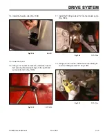
19. Using a 15/16” wrench, disconnect the right hand
hydrostatic pump lines (just marked) as follows:
A. Inlet line from the hydraulic oil filter (Fig. 1344).
Fig 1344
PICT-4636
B. Inlet line to the left hand hydrostatic pump (Fig.
1345).
Fig 1345
PICT-4641
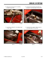
C. Case drain line (Fig. 1346).
Fig 1346
PICT-4643a
D. Hydraulic hose running from the “D” port on the
right hand hydrostatic pump to the upper fitting
on the left wheel motor (Fig. 1347).
Fig 1347
PICT-4644
Summary of Contents for Dingo TX 525
Page 1: ...TX525 Service Manual Sitework Systems Form No 492 9195...
Page 3: ...ii Rev 000 TX525 Service Manual 8 01 10 Revision 000 REVISIONS...
Page 11: ...x Rev 000 TX525 Service Manual TABLE OF CONTENTS THIS PAGE INTENTIONALLY LEFT BLANK...
Page 243: ...ENGINE 4 190 Rev 000 TX525 Service Manual THIS PAGE INTENTIONALLY LEFT BLANK...
Page 263: ...ELECTRICAL 5 20 Rev 000 TX525 Service Manual THIS PAGE INTENTIONALLY LEFT BLANK...
Page 377: ...HYDRAULIC SYSTEM 6 114 Rev 000 TX525 Service Manual THIS PAGE INTENTIONALLY LEFT BLANK...
Page 479: ...DRIVE SYSTEM 7 102 Rev 000 TX525 Service Manual THIS PAGE INTENTIONALLY LEFT BLANK...
Page 553: ...HYDRAULIC TESTING 9 20 Rev 000 TX525 Service Manual THIS PAGE INTENTIONALLY LEFT BLANK...


