DRIVE SYSTEM
7-15
TX525 Service Manual
Rev. 000
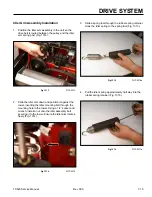
Idler Arm Assembly Installation
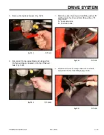
1. Position the idler arm assembly in the unit so the
drive belt is routed between the pulley and the idler
arm spring post (Fig. 1313).
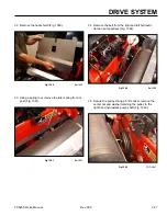
3. Slide a spring tool through the rubber spring retainer.
Hook the idler spring to the spring tool (Fig. 1315).
Fig 1313
PICT-5373
Fig 1315
PICT-5376a
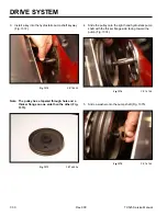
4. Pull the idler spring approximately half way into the
rubber spring retainer (Fig. 1316).
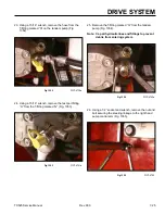
2. Slide the idler arm down and position it against the
tower, inserting the idler mounting bolt through the
mounting hole in the tower. Using a 1/2” socket and
wrench, install a nut onto the idler assembly bolt
securing it to the tower. Ensure the idler arm rotates
freely (Fig. 1314).
Fig 1316
PICT-5377a
Fig 1314
PICT-5370
Summary of Contents for Dingo TX 525
Page 1: ...TX525 Service Manual Sitework Systems Form No 492 9195...
Page 3: ...ii Rev 000 TX525 Service Manual 8 01 10 Revision 000 REVISIONS...
Page 11: ...x Rev 000 TX525 Service Manual TABLE OF CONTENTS THIS PAGE INTENTIONALLY LEFT BLANK...
Page 243: ...ENGINE 4 190 Rev 000 TX525 Service Manual THIS PAGE INTENTIONALLY LEFT BLANK...
Page 263: ...ELECTRICAL 5 20 Rev 000 TX525 Service Manual THIS PAGE INTENTIONALLY LEFT BLANK...
Page 377: ...HYDRAULIC SYSTEM 6 114 Rev 000 TX525 Service Manual THIS PAGE INTENTIONALLY LEFT BLANK...
Page 479: ...DRIVE SYSTEM 7 102 Rev 000 TX525 Service Manual THIS PAGE INTENTIONALLY LEFT BLANK...
Page 553: ...HYDRAULIC TESTING 9 20 Rev 000 TX525 Service Manual THIS PAGE INTENTIONALLY LEFT BLANK...


