ENGINE
4-47
TX525 Service Manual
Rev. 000
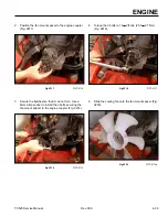
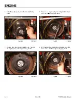
10. Position the pump mount to the engine (Fig. 0249).
Fig 0249
PICT-4861
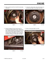
11. Using a 13mm socket, install 4 bolts securing the
pump mount to the engine housing (Fig. 0250).
Fig 0250
PICT-4863
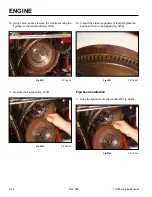
12. Ensure the belt is routed around the engine pulley
and install the belt onto the right and left hydraulic
traction pump pulleys (Fig. 0251).
Fig 0251
PICT-8902
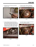
13. Maneuver the spring tool (Toro p/n 92-5771) be-
tween the drive belt and the tower. Hook the idler
spring to the spring post located on the tower and
remove the spring tool (Fig. 0252).
Fig 0252
Belt 007
Summary of Contents for Dingo TX 525
Page 1: ...TX525 Service Manual Sitework Systems Form No 492 9195...
Page 3: ...ii Rev 000 TX525 Service Manual 8 01 10 Revision 000 REVISIONS...
Page 11: ...x Rev 000 TX525 Service Manual TABLE OF CONTENTS THIS PAGE INTENTIONALLY LEFT BLANK...
Page 243: ...ENGINE 4 190 Rev 000 TX525 Service Manual THIS PAGE INTENTIONALLY LEFT BLANK...
Page 263: ...ELECTRICAL 5 20 Rev 000 TX525 Service Manual THIS PAGE INTENTIONALLY LEFT BLANK...
Page 377: ...HYDRAULIC SYSTEM 6 114 Rev 000 TX525 Service Manual THIS PAGE INTENTIONALLY LEFT BLANK...
Page 479: ...DRIVE SYSTEM 7 102 Rev 000 TX525 Service Manual THIS PAGE INTENTIONALLY LEFT BLANK...
Page 553: ...HYDRAULIC TESTING 9 20 Rev 000 TX525 Service Manual THIS PAGE INTENTIONALLY LEFT BLANK...


