ENGINE
4-96
Rev. 000
TX525 Service Manual
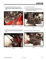
34. Using a 6mm Allen head socket, remove the 5 bolts
securing the engine pulley to the engine (Fig. 0438).
Fig 0438
PICT-5534-2
35. Remove the engine pulley from the engine (Fig.
0439).
Fig 0439
PICT-5537-2
36. To service the engine, refer to the Kubota D722/
D902 Tier 2 Diesel Engine Service Manual (Toro
Form No. 492-4796).
Engine Installation
Engine Component Installation
Fig 0440
PICT-5537-2
2. Using a 6mm Allen head socket, install 6 bolts
securing the engine pulley to the engine flywheel
(Fig. 0441).
Fig 0441
PICT-5534-2
1. Position the engine pulley to the engine (Fig. 0440).
Summary of Contents for Dingo TX 525
Page 1: ...TX525 Service Manual Sitework Systems Form No 492 9195...
Page 3: ...ii Rev 000 TX525 Service Manual 8 01 10 Revision 000 REVISIONS...
Page 11: ...x Rev 000 TX525 Service Manual TABLE OF CONTENTS THIS PAGE INTENTIONALLY LEFT BLANK...
Page 243: ...ENGINE 4 190 Rev 000 TX525 Service Manual THIS PAGE INTENTIONALLY LEFT BLANK...
Page 263: ...ELECTRICAL 5 20 Rev 000 TX525 Service Manual THIS PAGE INTENTIONALLY LEFT BLANK...
Page 377: ...HYDRAULIC SYSTEM 6 114 Rev 000 TX525 Service Manual THIS PAGE INTENTIONALLY LEFT BLANK...
Page 479: ...DRIVE SYSTEM 7 102 Rev 000 TX525 Service Manual THIS PAGE INTENTIONALLY LEFT BLANK...
Page 553: ...HYDRAULIC TESTING 9 20 Rev 000 TX525 Service Manual THIS PAGE INTENTIONALLY LEFT BLANK...


