DRIVE SYSTEM
7-1
TX525 Service Manual
Rev. 000
Lifting the Machine for Service
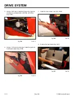
1. Place two pieces of approximately 2” (5.08cm) thick
wood blocks directly behind both tracks (Fig. 1261).
4. Raise the rear of the machine, remove the two wood
blocks and place a jack stand under each corner of
the frame (Fig. 1263).
Fig 1261
PICT-4245
Fig 1263
PICT-4248
5. Raise the hydraulic floor jack approximately 15”
(38.10cm) and position it at the front of the machine
(Fig. 1264).
2. Back the machine up onto the wood blocks.
3. Place a hydraulic floor jack under the rear frame of
the machine (Fig. 1262).
Fig 1264
PICT-4249
Fig 1262
PICT-4247
Summary of Contents for Dingo TX 525
Page 1: ...TX525 Service Manual Sitework Systems Form No 492 9195...
Page 3: ...ii Rev 000 TX525 Service Manual 8 01 10 Revision 000 REVISIONS...
Page 11: ...x Rev 000 TX525 Service Manual TABLE OF CONTENTS THIS PAGE INTENTIONALLY LEFT BLANK...
Page 243: ...ENGINE 4 190 Rev 000 TX525 Service Manual THIS PAGE INTENTIONALLY LEFT BLANK...
Page 263: ...ELECTRICAL 5 20 Rev 000 TX525 Service Manual THIS PAGE INTENTIONALLY LEFT BLANK...
Page 377: ...HYDRAULIC SYSTEM 6 114 Rev 000 TX525 Service Manual THIS PAGE INTENTIONALLY LEFT BLANK...
Page 479: ...DRIVE SYSTEM 7 102 Rev 000 TX525 Service Manual THIS PAGE INTENTIONALLY LEFT BLANK...
Page 553: ...HYDRAULIC TESTING 9 20 Rev 000 TX525 Service Manual THIS PAGE INTENTIONALLY LEFT BLANK...


