Engine Maintenance
9-25
Fuel Limit Screw
The fuel limit screw is not adjustable. It is equipped with an anti-tamper cap to fulfill requirements for CARB (California Air
Resources Board) emission regulations. Service technicians must be CARB certified to perform service on the fuel limit screw
for equipment operating in California.
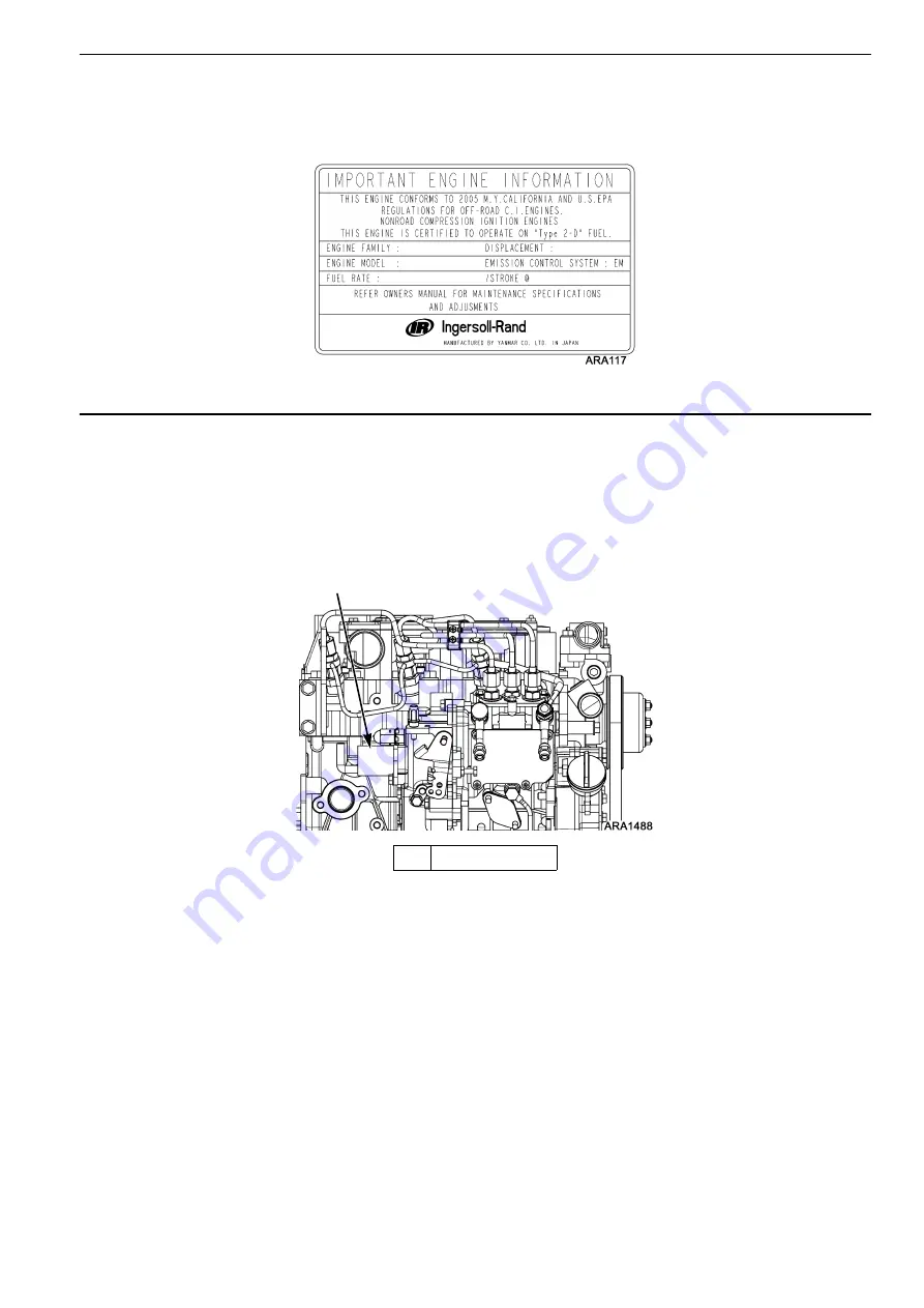
Emission Control Label
Fuel Solenoid
The fuel solenoid is located on the end of the injection pump. It contains two coils: the pull-in coil, and the hold-in coil. The
pull-in coil draws approximately 35 to 45 amps at 12 volts. The hold-in coil draws approximately 0.5 amps at 12 volts.
The pull-in coil must be momentarily energized to move the fuel rack to the on position. Once the fuel rack has been moved
to the on position, the hold-in coil will then hold the fuel rack in the on position until the 8D circuit is de-energized. The pull-in
coil must be de-energized after a few seconds to keep it from being damaged. The pull-in coil is controlled by the microprocessor
through the fuel solenoid pull in relay (K6).
Testing the Fuel Solenoid
The fuel solenoid pull-in coil will require 35 to 45 amps to turn on the fuel. The unit’s battery must be in good condition. If
the battery has enough power to crank the engine over, it has enough power to energize the fuel solenoid pull-in coil.
If you suspect that the engine does not run because the fuel solenoid is not operating correctly, use the following procedure:
1. Use the Mechanics/Premium HMI Control Panel to enter the Interface Board Test Mode. Refer to the appropriate
Microprocessor Diagnostic Manual for specific information about the Interface Board Test Mode.
2. Energize the run relay with the Interface Board Test Mode. The fuel solenoid relay is momentarily energized when the run
relay is energized with the Interface Board Test Mode. This energizes the fuel solenoid, which makes a definite click when
energized.
3. De-energize the run relay with the Interface Board Test Mode. This de-energizes the fuel solenoid, which makes a definite
click when de-energized.
4. Repeat steps 2 and 3 a few times to check the operation of the fuel solenoid.
1.
Fuel Solenoid
Fuel Solenoid Location
1
Summary of Contents for T-1000R
Page 14: ...Safety Precautions 2 6 Warning Decals 2e24151g0 ...
Page 34: ...Maintenance Inspection Schedule 4 10 ...
Page 57: ...Unit Description 5 23 Purge Mode UT Series 1 3 4 5 2 ...
Page 67: ...Unit Description 5 33 Zone 1 Cool and Zone 2 Cool UT SPECTRUM Units ...
Page 69: ...Unit Description 5 35 Purge Mode UT SPECTRUM Units ...
Page 71: ...Unit Description 5 37 Zone 1 Cool and Zone 2 Heat UT SPECTRUM Units ...
Page 72: ...Unit Description 5 38 ...
Page 74: ...Diesel Electric Menu 6 28 Adjust Brightness 6 29 Time 6 30 ...
Page 120: ...Operating Instructions Standard HMI 7 18 ...
Page 152: ...Engine Maintenance 9 14 T Series Fuel and Oil System Components TK 376 ...
Page 154: ...Engine Maintenance 9 16 T Series Fuel and Oil System Components TK 270 ...
Page 156: ...Engine Maintenance 9 18 UT Series Fuel System Components AMA768 ...
Page 172: ...Engine Maintenance 9 34 T Series Engine Mounting Components for 2 Cylinder Engine ...
Page 184: ...Engine Maintenance 9 46 ...
Page 238: ...Refrigeration Maintenance 10 54 ...
Page 246: ...Clutch Maintenance 11 8 ...
Page 258: ...Structural Maintenance 12 12 ...
Page 264: ...Mechanical Diagnosis 13 6 ...
Page 265: ...14 Electric Standby Diagnosis ...
Page 268: ...Electric Standby Diagnosis 14 4 ...
Page 269: ...15 Refrigeration System Diagnosis ...
Page 272: ...Refrigeration System Diagnosis 15 4 ...
Page 280: ...Remote Evaporators 16 8 ...


