Refrigeration Maintenance
10-11
Charging procedure:
1. Install a calibrated gauge manifold on the unit.
2. Recover residual refrigerant charge and evacuate the system completely.
3. Make a quick calculation of the approximate required refrigerant charge. Refer to the table above for initial charge
calculations.
4. Liquid charge the unit as per Thermo King procedures with the exact calculated amount from step 3, utilising weighing
scales to ensure accurate measurement.
5. Run unit in high speed cool with a set point of -20°C in all zones and with any separation walls stowed in the open position.
Note: Carry out manual defrost of remote evaporators and then host unit evaporator at -15°C to ensure all ice is cleared
from all evaporators.
6. Maintain unit running in high speed cool and check refrigerant level. Cover condenser to raise discharge pressure to approxi
mately 325 psig to 350 psig (22 Bar to 23 Bar gauge). Ball in receiver sight glass should be between
⅓
and ½ full, if the
ball is not floating add charge at 0.25 kg increments until the ball floats.
7. If the starting charge level is exceeded by 1 kg, this indicates that the unit may now be overcharged and the installation
should be checked for possible problems.
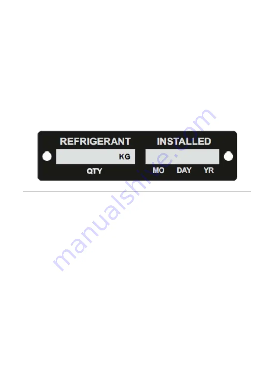
8. Once the system is charged and prior to placing the unit into service, ensure the correct refrigerant charge is entered into the
refrigerant charge decal on the frame near the serial plate. This must be filled in so the next technician knows the quantity
required for the system. Please ensure that the installed date information is also entered.
Refrigerant Gauge Removal
1. Operate the unit in cool mode.
2. Backseat the discharge service valve.
3. Open both service manifold hand valves.
4. Front seat the suction service valve and pump down the compressor to a 20 in. Hg vacuum (-68 kPa).
5. Stop the unit.
6. Establish a compressor crankcase pressure between 1 and 3 psig (7 and 21 kPa).
7. Remove the gauge line from the suction service valve and cap the service port.
8. Remove the gauge line from the discharge service valve and cap the service port.
9. Back seat the suction service valve.
10. Install and tighten service valve stem caps.
11. Unit is ready for a functional check out.
Summary of Contents for T-1000R
Page 14: ...Safety Precautions 2 6 Warning Decals 2e24151g0 ...
Page 34: ...Maintenance Inspection Schedule 4 10 ...
Page 57: ...Unit Description 5 23 Purge Mode UT Series 1 3 4 5 2 ...
Page 67: ...Unit Description 5 33 Zone 1 Cool and Zone 2 Cool UT SPECTRUM Units ...
Page 69: ...Unit Description 5 35 Purge Mode UT SPECTRUM Units ...
Page 71: ...Unit Description 5 37 Zone 1 Cool and Zone 2 Heat UT SPECTRUM Units ...
Page 72: ...Unit Description 5 38 ...
Page 74: ...Diesel Electric Menu 6 28 Adjust Brightness 6 29 Time 6 30 ...
Page 120: ...Operating Instructions Standard HMI 7 18 ...
Page 152: ...Engine Maintenance 9 14 T Series Fuel and Oil System Components TK 376 ...
Page 154: ...Engine Maintenance 9 16 T Series Fuel and Oil System Components TK 270 ...
Page 156: ...Engine Maintenance 9 18 UT Series Fuel System Components AMA768 ...
Page 172: ...Engine Maintenance 9 34 T Series Engine Mounting Components for 2 Cylinder Engine ...
Page 184: ...Engine Maintenance 9 46 ...
Page 238: ...Refrigeration Maintenance 10 54 ...
Page 246: ...Clutch Maintenance 11 8 ...
Page 258: ...Structural Maintenance 12 12 ...
Page 264: ...Mechanical Diagnosis 13 6 ...
Page 265: ...14 Electric Standby Diagnosis ...
Page 268: ...Electric Standby Diagnosis 14 4 ...
Page 269: ...15 Refrigeration System Diagnosis ...
Page 272: ...Refrigeration System Diagnosis 15 4 ...
Page 280: ...Remote Evaporators 16 8 ...


