


84 User Manual
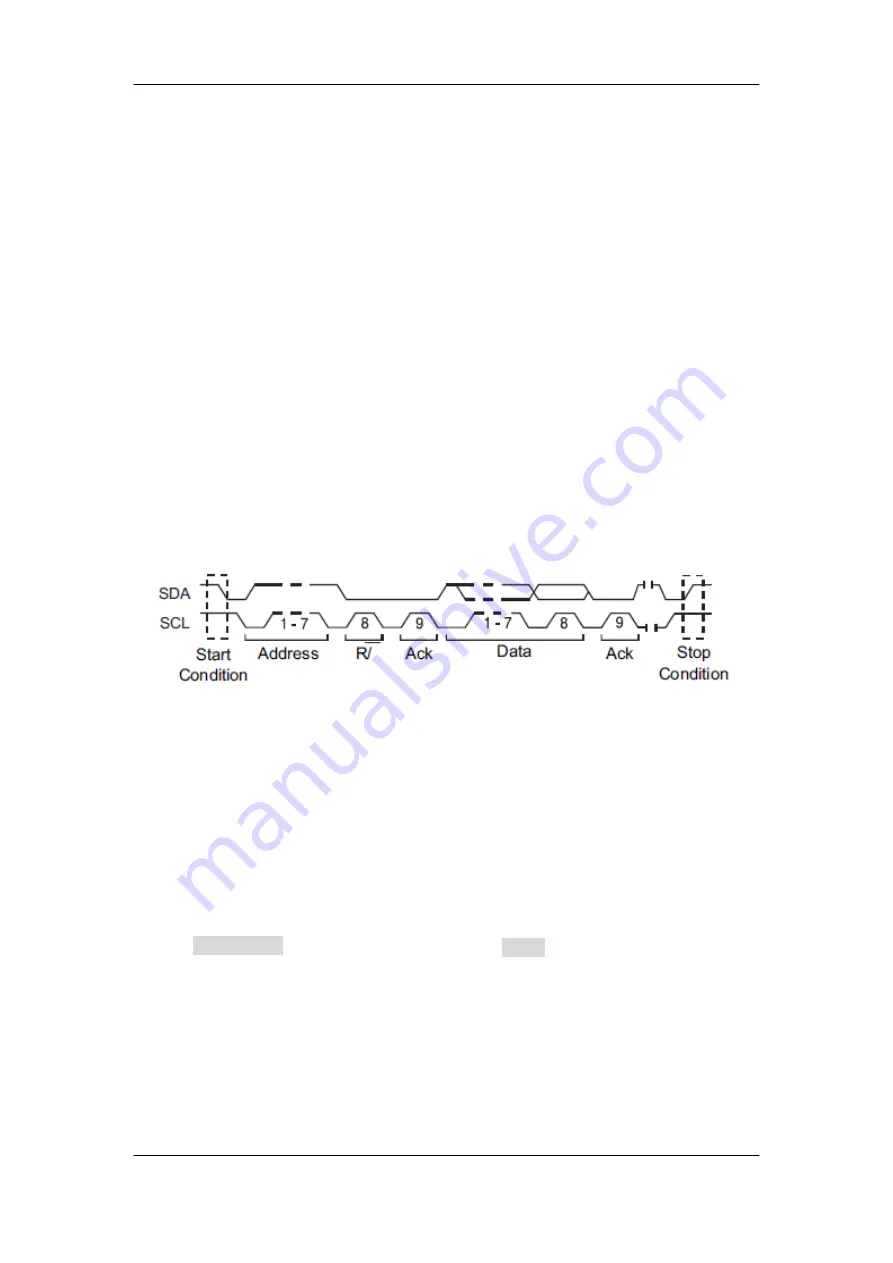
I2C Triggering
This part introduces the nine trigger conditions (Start, Stop, Restart, No Ack, EEPROM,
7 Bit Addr & Data, 10 Bit Addr & Data and Data Length) and the methods of setting them.
Introduction to the trigger conditions
●
Start Condition
— the oscilloscope will be triggered when the SDA signal
transitions from a high to a low while the SCL clock is high. If it is the trigger
condition (including frame triggers), a restart will be treated as a “Start condition”.
●
Stop Condition
— the oscilloscope will be triggered when SDA transitions from
low to high while the SCL is high.
●
Restart
— the oscilloscope will be triggered when another “Start condition” occurs
before a “Stop condition”
.
●
No Ack
— the oscilloscope will be triggered when SDA data is high during any
SCL’s ACK bit.
●
EEPROM
— the trigger searches for EEPROM control byte (the value is 1010xxx)
on the SDA bus. And there is a Read bit and a ACK bit following EEPROM. Using
Limit Range
softkey to set the qualifier and
Data1
softkey to set the data’s value.
If EEPROM’s data is greater (less, equal) than Data1, the oscilloscope will be
triggered at the edge of ACK bit behind Data byte. It’s unnecessary that the Data
byte musts follow the EEPROM.
Summary of Contents for T3DSO1000
Page 1: ...User Manual T3DSO1000 T3DSO1000A Series Digital Oscilloscope...
Page 62: ...44 User Manual Figure 16 x Interpolation Figure 17 Sinx x Interpolation...
Page 90: ...72 User Manual Figure 32 Relative Window Trigger...
Page 92: ...74 User Manual Figure 33 Interval Trigger...
Page 98: ...80 User Manual Universal Knob to select the desired value Figure 37 Pattern Trigger...
Page 118: ...100 User Manual Figure 50 UART Trigger...
Page 145: ...User Manual 127 function output Figure 63 Square Root...
Page 205: ...User Manual 187 Figure 100 Option Information...