6. STEERING SYSTEM
- 84 -
6.1.3 ACTUATOR
The actuator is a ball and nut screw type. The screw lengthens and shortens according to motor
operation.
Motor operation is transmitted to the ball and nut unit after its speed is reduced by two gears. The
ball and nut unit is supported by two taper roller bearings on the gearbox.
The actuator is installed with its tube side fitted to the frame of the truck by a universal joint and with
its screw side fitted to the center arm of the axle by a ball joint.
6.1.4 REAR AXLE
The rear axle unit is of welded construction with a box-shaped cross section, consisting of an axle,
center arm, tie rods, and knuckles.
The rear axle support with a bushing press-fitted is attached to the support pins located at the front
and rear of the axle. The support is bolted to the rear frame. The axle is so mounted as to be cradled
with the front and rear support pins as an axis.
The knuckle attached to each end of the axle is so structured as can turn clockwise and
counterclockwise around the king pin. The rear wheel hub is mounted on the spindle of the knuckle
through two taper roller bearings. On the hub installed is the wheel with hub bolts and nuts. The taper
roller bearing at the king pin side has a single-side seal to keep tight the grease filled between the hub
and the knuckle.
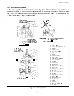
(Red) +
(Black) -
EPS MOTOR
PINION GEAR
IDLE GEAR
BOOT
BALL JOINT
BALL NUT
BALL SCREW
BREATHER
UNIVERSAL JOINT
Fig. 6.5
Actuator
View looking from A
Summary of Contents for FB10-7
Page 2: ......
Page 4: ...No SEB 81BBE...
Page 8: ...No SEB 81BBE...
Page 9: ...No SEB 81BBE Fig 1 Overall Dimensions Unit mm in...
Page 10: ...No SEB 81BBE...
Page 28: ...1 BATTERY AND CHARGER 16 NOTE...
Page 30: ...2 MOTORS 18 DRIVE UNIT Fig 2 1 Drive Motor Installation DRIVE AXLE DRIVE MOTOR...
Page 42: ...3 CONTROL SYSTEM 30 Fig 3 2 Inverter Assembly 1 0 to 2 5 ton Trucks...
Page 43: ...31 3 CONTROL SYSTEM Fig 3 3 Inverter Assembly 3 0 to 3 5 ton Trucks...
Page 44: ...3 CONTROL SYSTEM 32 Fig 3 4 Controller Wiring 1 0 to 2 5 ton Trucks...
Page 45: ...33 3 CONTROL SYSTEM Fig 3 5 Controller Wiring 3 0 to 3 5 ton Trucks...
Page 133: ...7 HYDRAULIC SYSTEM 121 Fig 7 27 Remove the oil seal from the front cover...
Page 160: ...8 LOAD HANDLING SYSTEM 148 NOTE...

