5. BRAKE SYSTEM
- 74 -
5.2.3 REASSEMBLING WHEEL BRAKE
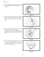
(1) Apply brake fluid to the cup and piston of the wheel cylinder. Install the spring, piston cup, piston
and boot in this order.
(2) Install the wheel cylinder on the backing plate.
Tightening torque: 17.7 to 26.5 N-m {180 to 270 kgf-cm} [156.7 to 234.5 lbf-in.]
(3) Install the backing plate on the drive axle.
Tightening torque: 117.7 to 137.3 N-m {1200 to 1400 kgf-cm} [1042 to 1215 lbf-in.]
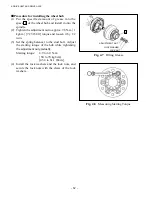
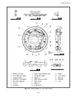
(4) Apply high-temperature grease to the points shown in Fig. 5.23, using caution to keep grease away
from the lining.
(a) Shoe contacting surface on the
backing plate
(b) Anchor pin
(c) Cable guide surface contacting
the adjuster cable
(d) Parking brake lever pin
(e) Threaded area of the adjuster
and the other rotation areas
(5) Install the parking brake cable with the E retainer.
(6) Install the shoe with the hold-down spring.
(7) Insert the spring into the strut and attach the strut to the shoe.
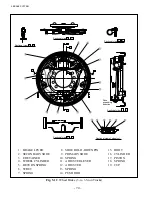
Fig. 5.24
Fig. 5.23
Summary of Contents for FB10-7
Page 2: ......
Page 4: ...No SEB 81BBE...
Page 8: ...No SEB 81BBE...
Page 9: ...No SEB 81BBE Fig 1 Overall Dimensions Unit mm in...
Page 10: ...No SEB 81BBE...
Page 28: ...1 BATTERY AND CHARGER 16 NOTE...
Page 30: ...2 MOTORS 18 DRIVE UNIT Fig 2 1 Drive Motor Installation DRIVE AXLE DRIVE MOTOR...
Page 42: ...3 CONTROL SYSTEM 30 Fig 3 2 Inverter Assembly 1 0 to 2 5 ton Trucks...
Page 43: ...31 3 CONTROL SYSTEM Fig 3 3 Inverter Assembly 3 0 to 3 5 ton Trucks...
Page 44: ...3 CONTROL SYSTEM 32 Fig 3 4 Controller Wiring 1 0 to 2 5 ton Trucks...
Page 45: ...33 3 CONTROL SYSTEM Fig 3 5 Controller Wiring 3 0 to 3 5 ton Trucks...
Page 133: ...7 HYDRAULIC SYSTEM 121 Fig 7 27 Remove the oil seal from the front cover...
Page 160: ...8 LOAD HANDLING SYSTEM 148 NOTE...

