2. MOTORS
- 24 -
(3) Periodic inspection
■
Inspection criteria
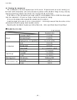
Check the motor at periodic intervals, referring to the following troubleshooting chart. If the motor is
used under a severe working condition, earlier or more frequent preventive maintenance is required.
Operation time
more than 12 hours/day
8 – 12 hours/day
Inspection interval
Once a year
Once every two years
Location
Roller
bearing
Tightened
areas
Terminals
Stator
and rotor
assembly
Speed
sensor
Thermo
sensor
Painting
Cleanliness
Check item
Bearing (sealed type)
Joined parts
Fasteners
Joined areas
Connections
Lead wire
Resistance between
terminals
Iron core
Coil and insulation at
connections
Measure resistance
Measure gap
Measure resistance
Damage
Deposit of
contaminants or dust
Criteria
Check grease leaks, noise, adherence of dust
visually or audibly.
Check for damage or rough surface due to
corrosion visually.
Check for looseness, corrosion or seizure
visually or by tapping.
Check for damage or rough surface due to
corrosion visually.
Visually check that connections are correct and
not loose, and that proper insulation is ensured.
Check coating for damage visually.
0.0063
Ω
± 5% (20°C or 68°F)
Check for adherence of dust visually.
Insulation resistance is more than 1M
Ω
.
(Use 500 V megger)
620 ± 60
Ω
(20°C or 68°F)
0.7 ± 0.3 mm [0.028 ± 0.012 in.]
13.04 k
Ω
± 10% (20°C or 68°F)
Check for damage, discoloration, peeling, or
corrosion visually.
Check for contamination, adherence of dust or
corrosion visually.
Remedy
Replace.
Clean.
Retighten, apply anti-
rust or replace.
Clean.
Retighten.
Ask specialist for
repair.
Ask specialist for
repair.
Clean.
Clean.
Heat.
Varnish.
Replace.
Ask specialist for
adjustment.
Ask specialist for
repair.
Apply anti-rust.
Paint again.
Clean or apply anti-
rust.
Paint.
Summary of Contents for FB10-7
Page 2: ......
Page 4: ...No SEB 81BBE...
Page 8: ...No SEB 81BBE...
Page 9: ...No SEB 81BBE Fig 1 Overall Dimensions Unit mm in...
Page 10: ...No SEB 81BBE...
Page 28: ...1 BATTERY AND CHARGER 16 NOTE...
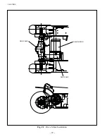
Page 30: ...2 MOTORS 18 DRIVE UNIT Fig 2 1 Drive Motor Installation DRIVE AXLE DRIVE MOTOR...
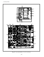
Page 42: ...3 CONTROL SYSTEM 30 Fig 3 2 Inverter Assembly 1 0 to 2 5 ton Trucks...
Page 43: ...31 3 CONTROL SYSTEM Fig 3 3 Inverter Assembly 3 0 to 3 5 ton Trucks...
Page 44: ...3 CONTROL SYSTEM 32 Fig 3 4 Controller Wiring 1 0 to 2 5 ton Trucks...
Page 45: ...33 3 CONTROL SYSTEM Fig 3 5 Controller Wiring 3 0 to 3 5 ton Trucks...
Page 133: ...7 HYDRAULIC SYSTEM 121 Fig 7 27 Remove the oil seal from the front cover...
Page 160: ...8 LOAD HANDLING SYSTEM 148 NOTE...


