7. HYDRAULIC SYSTEM
- 116 -
7.1.6 TILT CYLINDER
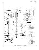
The tilt cylinder is a double-acting type. The piston rod end is supported by the mast, and the
cylinder tail by a pin on the frame. Two tilt cylinders are mounted on both sides of the truck, one at
each.
The tilt cylinder consists of a cylinder body, cylinder cap, piston and piston rod. The piston is
attached to the piston rod with a nut, and is provided with two packings and one wear ring on its
circumference. It is slid by hydraulic oil along the inner surface of the cylinder.
The cylinder cap is provided inside with a press-fitted bushing, packing, and dust seal which provide
oil tightness for the piston rod and in the cylinder cap, and also supports piston rod.
When the tilt lever is pushed forward, high-pressure oil flows into the tilt cylinder through its tail.
The oil then moves the piston forward, high-pressure oil flows into the tilt cylinder through its tail. The
oil then moves the piston forward, causing the mast to tilt forward by 6 degrees.
When it is pulled toward the operator, high-pressure oil enters the tilt cylinder from the cylinder cap
side. The oil then pushes back the piston, causing the mast to tilt backward by 12 degrees.
1. JOINT
2. DUST SEAL
3. BUSHING
4. “O”-RING
5. PACKING
6. CYLINDER CAP
7. “O”-RING
Fig. 7.15
Tilt Cylinder
8. LOCK RING
9. ROD
10. CYLINDER
11. PACKING
12. PISTON
13. LOCK NUT
Summary of Contents for FB10-7
Page 2: ......
Page 4: ...No SEB 81BBE...
Page 8: ...No SEB 81BBE...
Page 9: ...No SEB 81BBE Fig 1 Overall Dimensions Unit mm in...
Page 10: ...No SEB 81BBE...
Page 28: ...1 BATTERY AND CHARGER 16 NOTE...
Page 30: ...2 MOTORS 18 DRIVE UNIT Fig 2 1 Drive Motor Installation DRIVE AXLE DRIVE MOTOR...
Page 42: ...3 CONTROL SYSTEM 30 Fig 3 2 Inverter Assembly 1 0 to 2 5 ton Trucks...
Page 43: ...31 3 CONTROL SYSTEM Fig 3 3 Inverter Assembly 3 0 to 3 5 ton Trucks...
Page 44: ...3 CONTROL SYSTEM 32 Fig 3 4 Controller Wiring 1 0 to 2 5 ton Trucks...
Page 45: ...33 3 CONTROL SYSTEM Fig 3 5 Controller Wiring 3 0 to 3 5 ton Trucks...
Page 133: ...7 HYDRAULIC SYSTEM 121 Fig 7 27 Remove the oil seal from the front cover...
Page 160: ...8 LOAD HANDLING SYSTEM 148 NOTE...


