6. STEERING SYSTEM
- 79 -
6. STEERING SYSTEM
Model
FB10-7 FB15-7
FB20-7 FB25-7
FB30-7
FB18-7
FB25-7LB FB25-7V
FB30-7V
Item
FB35-7S
Steering system
Type
Rear wheel steering, electric power steering
Steering gear
Type
Ball nut type
Name
PU41
Reduction ratio
18.9
Operating angle
92°
Worm returning angle
Left
Handwheel dia.
360 mm [14.2 in.]
Actuator
Type
Motor-driven, ball nut type
Rated voltage of motor
48 V
←
72 V
Rated output of motor
350 W
550 W
←
Stroke
235 mm [9.3 in.]
←
←
Controller
Type
Voltage controlling type
Rated voltage
48 V
←
72 V
Current limit
Max. ±40 A
Max. ±45 A
←
Rear axle
Type
Elliot type
←
←
Steering angle
(Inner wheel)
85.8°
83.5°
←
(Outer wheel)
55.6°
56.4°
←
King pin spacing
735 mm [28.9 in.]
740 mm [29.1 in.]
←
King pin tilt
0°
←
←
Camber
0°
1°
←
Caster
0
←
←
Toe-in
0
←
←
Trail
0
←
←
Wheel
Tire size
16 x 6 – 8 10PR
18 x 7 – 8 14PR
←
3.5 t: 18 x 7 – 8
Rim size
4.25 x DT
←
←
Inflation pressure
850 kPa {8.5 kgf/cm
2
} 900 kPa {9.0 kgf/cm
2
}
– * –
[120.9 psi]
[128.0 psi]
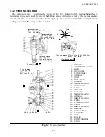
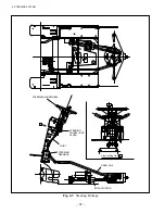
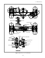
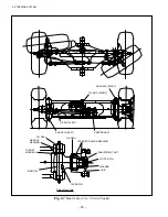
6.1 GENERAL DESCRIPTION
The steering system consists of a steering gear, actuator, controller, and axle. The steering handwheel
operating force is boosted by the motor-driven actuator.
Summary of Contents for FB10-7
Page 2: ......
Page 4: ...No SEB 81BBE...
Page 8: ...No SEB 81BBE...
Page 9: ...No SEB 81BBE Fig 1 Overall Dimensions Unit mm in...
Page 10: ...No SEB 81BBE...
Page 28: ...1 BATTERY AND CHARGER 16 NOTE...
Page 30: ...2 MOTORS 18 DRIVE UNIT Fig 2 1 Drive Motor Installation DRIVE AXLE DRIVE MOTOR...
Page 42: ...3 CONTROL SYSTEM 30 Fig 3 2 Inverter Assembly 1 0 to 2 5 ton Trucks...
Page 43: ...31 3 CONTROL SYSTEM Fig 3 3 Inverter Assembly 3 0 to 3 5 ton Trucks...
Page 44: ...3 CONTROL SYSTEM 32 Fig 3 4 Controller Wiring 1 0 to 2 5 ton Trucks...
Page 45: ...33 3 CONTROL SYSTEM Fig 3 5 Controller Wiring 3 0 to 3 5 ton Trucks...
Page 133: ...7 HYDRAULIC SYSTEM 121 Fig 7 27 Remove the oil seal from the front cover...
Page 160: ...8 LOAD HANDLING SYSTEM 148 NOTE...

