5. BRAKE SYSTEM
- 66 -
(1) Wheel brake operation
The wheel cylinder pushes the primary and
secondary shoes against the brake drum with an
equal force. The shoes are kept turning with the
brake drum until the top of the secondary shoe comes
in contact with the anchor pin.
When the secondary shoe comes in contact
with the anchor pin, the friction force is generated
between the brake lining and the brake drum, and
the primary shoe pushes the secondary shoe with a
stronger force than the operation force of the wheel
cylinder. Powerful braking force is thus achieved.
(See Fig. 5.4)
In backward travel, the braking force works in the
reverse direction of forward travel. (See Fig. 5.5)
(2) Parking brake
The parking brake unit is built in the wheel brake,
and consists of a lever and strut.
The lever is installed on the primary shoe side
with a pin. Movement of the lever is also transmitted
to the secondary shoe side through the strut.
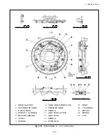
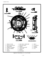
5.1.3 WHEEL BRAKE
The wheel brake is duo-servo type, and is mounted
on each of the both ends of the drive axle.
The wheel brake is composed of two pairs of
brake shoes, a wheel cylinder and adjuster.
One end of the brake shoe is contacted with the
anchor pin and another end is contacted with the
adjuster. The brake shoes are pushed against the
backing plate through the shoe hold-down spring and
shoe hold-down pin.
The parking brake mechanism and the automatic
clearance adjuster are also built in the wheel brake.
Fig. 5.6
Parking Brake
Fig. 5.4
Braking Operation in Forward Travel
Fig. 5.5
Braking Operation in Backward Travel
ADJUSTER
PRIMARY SHOE
Rotation direction of
drum
ANCHOR PIN
PIN
LEVER
SECONDARY SHOE
STRUT
Working force
Secondary
Primary
Working force
Secondary
Primary
Summary of Contents for FB10-7
Page 2: ......
Page 4: ...No SEB 81BBE...
Page 8: ...No SEB 81BBE...
Page 9: ...No SEB 81BBE Fig 1 Overall Dimensions Unit mm in...
Page 10: ...No SEB 81BBE...
Page 28: ...1 BATTERY AND CHARGER 16 NOTE...
Page 30: ...2 MOTORS 18 DRIVE UNIT Fig 2 1 Drive Motor Installation DRIVE AXLE DRIVE MOTOR...
Page 42: ...3 CONTROL SYSTEM 30 Fig 3 2 Inverter Assembly 1 0 to 2 5 ton Trucks...
Page 43: ...31 3 CONTROL SYSTEM Fig 3 3 Inverter Assembly 3 0 to 3 5 ton Trucks...
Page 44: ...3 CONTROL SYSTEM 32 Fig 3 4 Controller Wiring 1 0 to 2 5 ton Trucks...
Page 45: ...33 3 CONTROL SYSTEM Fig 3 5 Controller Wiring 3 0 to 3 5 ton Trucks...
Page 133: ...7 HYDRAULIC SYSTEM 121 Fig 7 27 Remove the oil seal from the front cover...
Page 160: ...8 LOAD HANDLING SYSTEM 148 NOTE...


