6. STEERING SYSTEM
- 81 -
6.1.2 STEERING GEARBOX
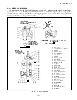
The steering gearbox is constructed as shown in Fig. 6.2. Rotation of the steering handwheel is
transmitted to the sector shaft by way of the ball nut screw. At the lower part of the steering gearbox
unit is located the potentiometer which converts slight up-and-down movement of the steering shaft into
a voltage and sends the voltage to the controller.
1. LOCK NUT
2. ADJUSTMENT SCREW
3. SHIMS
4. SIDE COVER
5. SECTOR SHAFT
6. OIL SEAL
7. SHAFT
8. DUST COVER
9. OIL SEAL
10. NEEDLE BEARING
11. REAR COVER
12. O-RING
13. GEARBOX
14. BALL NUT
15. NEEDLE BEARING
16. OIL SEAL
17. THRUST BEARING
18. SPRING
19. SENSOR HOUSING
20. O-RING
21. THRUST BEARING
22. LOCK NUT
23. FRONT COVER
24. SLIDE RING
25. ARM
26. ROLLER
27. POTENTIOMETER
28. O-RING
Fig. 6.2
Steering Gearbox
Tightening torque:
19.6 to 29.4 N-m {200 to 300 kg-cm}
[173.5 to 260.2 lbf-in.]
Tightening torque:
16.7 to 27.5 N-m
{170 to 280 kgf-cm}
[147.8 to 243.4 lbf-in.]
Tightening torque:
137.3 to 176.5 N-m
{1400 to 1800 kgf-cm}
[1215 to 1562 lbf-in.]
View looking from B
Tightening torque: 37.3 to 53 N-m {380 to 540 kgf-cm}
[330.1 to 469.1 lbf-in.]
Black
Yellow
Red
White
Green
Blue
Tightening torque:
16.7 to 27.5 N-m
{170 to 280 kgf-cm}
[147.8 to 243.4 lbf-in.]
Sectional view A - A
Summary of Contents for FB10-7
Page 2: ......
Page 4: ...No SEB 81BBE...
Page 8: ...No SEB 81BBE...
Page 9: ...No SEB 81BBE Fig 1 Overall Dimensions Unit mm in...
Page 10: ...No SEB 81BBE...
Page 28: ...1 BATTERY AND CHARGER 16 NOTE...
Page 30: ...2 MOTORS 18 DRIVE UNIT Fig 2 1 Drive Motor Installation DRIVE AXLE DRIVE MOTOR...
Page 42: ...3 CONTROL SYSTEM 30 Fig 3 2 Inverter Assembly 1 0 to 2 5 ton Trucks...
Page 43: ...31 3 CONTROL SYSTEM Fig 3 3 Inverter Assembly 3 0 to 3 5 ton Trucks...
Page 44: ...3 CONTROL SYSTEM 32 Fig 3 4 Controller Wiring 1 0 to 2 5 ton Trucks...
Page 45: ...33 3 CONTROL SYSTEM Fig 3 5 Controller Wiring 3 0 to 3 5 ton Trucks...
Page 133: ...7 HYDRAULIC SYSTEM 121 Fig 7 27 Remove the oil seal from the front cover...
Page 160: ...8 LOAD HANDLING SYSTEM 148 NOTE...


