2. MOTORS
- 23 -
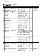
(2) Check the following items with the motor stopped
Check item
Tightened areas
Terminals
Location
Screws and
nuts
Connections
Lead wires
Criteria
No looseness, adherence of dust, or corrosion
allowed.
Check visually and by tapping.
Connections are correct and not loose.
Proper insulation is ensured.
Visual check.
No damage to coating allowed.
Visual check.
Remedy
Retighten, clean or
paint.
Retighten.
Check for insulation.
Ask specialist for
repair.
2.2 MAINTENANCE
2.2.1 DRIVE MOTOR
(1) Check the following points with the motor running
Remedy
If too much deposit of
dust is found, stop the
motor and clean.
Return to normal
condition.
Return to normal
condition.
If allowable limit is
exceeded, stop the
motor and remove the
cause.
If any defect is found,
stop the motor and
remove the cause.
Check item
Dust
Foreign
matter,
splash, liquid
Temperature rise
Vibration
Noise
Location
Motor frame
Motor frame
Motor frame,
bearing
Motor frame,
bearing, and
cover
Motor frame,
bearing, cover
Criteria
No remarkable deposit of dust allowed
compared with usual operation.
Usual temperature rise.
Visual check.
No remarkable change allowed compared with
usual operation.
Visual check.
No remarkable rise in temperature allowed
compared with usual operation.
Temperature is below specified values:
Motor frame: 80°C [176°F]
Bearing: 55°C [131°F]
No remarkable vibration or amplitude increase
allowed compared with usual operation.
Visual and audible checks.
No remarkable noise or sound allowed compared
with usual operation.
Using a sound-check rod, check against new
product.
Audible check.
Environment
Summary of Contents for FB10-7
Page 2: ......
Page 4: ...No SEB 81BBE...
Page 8: ...No SEB 81BBE...
Page 9: ...No SEB 81BBE Fig 1 Overall Dimensions Unit mm in...
Page 10: ...No SEB 81BBE...
Page 28: ...1 BATTERY AND CHARGER 16 NOTE...
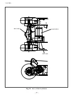
Page 30: ...2 MOTORS 18 DRIVE UNIT Fig 2 1 Drive Motor Installation DRIVE AXLE DRIVE MOTOR...
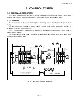
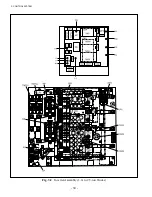
Page 42: ...3 CONTROL SYSTEM 30 Fig 3 2 Inverter Assembly 1 0 to 2 5 ton Trucks...
Page 43: ...31 3 CONTROL SYSTEM Fig 3 3 Inverter Assembly 3 0 to 3 5 ton Trucks...
Page 44: ...3 CONTROL SYSTEM 32 Fig 3 4 Controller Wiring 1 0 to 2 5 ton Trucks...
Page 45: ...33 3 CONTROL SYSTEM Fig 3 5 Controller Wiring 3 0 to 3 5 ton Trucks...
Page 133: ...7 HYDRAULIC SYSTEM 121 Fig 7 27 Remove the oil seal from the front cover...
Page 160: ...8 LOAD HANDLING SYSTEM 148 NOTE...

