5. BRAKE SYSTEM
- 77 -
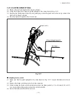
5.2.5 ADJUSTING BRAKE PEDAL
(1) Shorten the push rod length of the master cylinder.
(2) Using the stopper bolt, adjust the pedal upheight to the value shown in Fig. 5.29.
(3) Keeping the pedal pressed down by the pedal play, extend the push rod so that its tip contacts the
piston of the master cylinder.
(4) Securely tighten the push rod by its lock nut.
■
Adjusting brake switch
(1) Make sure that the pedal upheight is the value shown in Fig. 5.29. Loosen the brake switch lock
nut.
(2) Remove the brake switch lead wire from the connector.
(3) While turning the brake switch and pressing down the brake pedal by 15 to 20 mm [0.59 to 0.79
in.], check and find the position where the switch turns ON.
(4) Secure the brake switch with the lock nut.
Pedal height:
90 mm [3.54 in.]
Fig. 5.29
BRAKE SWITCH
Brake switch operating direction:
5 – 10 mm [0.1969 – 0.39 in.]
Summary of Contents for FB10-7
Page 2: ......
Page 4: ...No SEB 81BBE...
Page 8: ...No SEB 81BBE...
Page 9: ...No SEB 81BBE Fig 1 Overall Dimensions Unit mm in...
Page 10: ...No SEB 81BBE...
Page 28: ...1 BATTERY AND CHARGER 16 NOTE...
Page 30: ...2 MOTORS 18 DRIVE UNIT Fig 2 1 Drive Motor Installation DRIVE AXLE DRIVE MOTOR...
Page 42: ...3 CONTROL SYSTEM 30 Fig 3 2 Inverter Assembly 1 0 to 2 5 ton Trucks...
Page 43: ...31 3 CONTROL SYSTEM Fig 3 3 Inverter Assembly 3 0 to 3 5 ton Trucks...
Page 44: ...3 CONTROL SYSTEM 32 Fig 3 4 Controller Wiring 1 0 to 2 5 ton Trucks...
Page 45: ...33 3 CONTROL SYSTEM Fig 3 5 Controller Wiring 3 0 to 3 5 ton Trucks...
Page 133: ...7 HYDRAULIC SYSTEM 121 Fig 7 27 Remove the oil seal from the front cover...
Page 160: ...8 LOAD HANDLING SYSTEM 148 NOTE...


