8. LOAD HANDLING SYSTEM
- 143 -
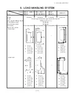
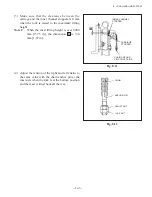
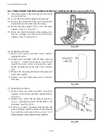
Fig. 8.11
Fig. 8.12
(3) Make sure that the clearance between the
carriage and the inner channel stoppers is 0 mm
when the fork is raised to the maximum lifting
height
Note 1:
When the mast lifting height is over 4000
mm [157.5 in.], the dimension
B
is +50
mm [1.97 in.].
CHAIN ANCHOR
PIN AT MAST SIDE
LOCK NUT
(4) Adjust the tension of the right and left chains to
the same value with the chain anchor pin at the
mast side when the fork is at the bottom position
and the mast is tilted back all the way.
CHAIN
ANCHOR PIN
ADJUST NUT
INNER CHANNEL
STOPPER
CARRIAGE
STOPPER
Summary of Contents for FB10-7
Page 2: ......
Page 4: ...No SEB 81BBE...
Page 8: ...No SEB 81BBE...
Page 9: ...No SEB 81BBE Fig 1 Overall Dimensions Unit mm in...
Page 10: ...No SEB 81BBE...
Page 28: ...1 BATTERY AND CHARGER 16 NOTE...
Page 30: ...2 MOTORS 18 DRIVE UNIT Fig 2 1 Drive Motor Installation DRIVE AXLE DRIVE MOTOR...
Page 42: ...3 CONTROL SYSTEM 30 Fig 3 2 Inverter Assembly 1 0 to 2 5 ton Trucks...
Page 43: ...31 3 CONTROL SYSTEM Fig 3 3 Inverter Assembly 3 0 to 3 5 ton Trucks...
Page 44: ...3 CONTROL SYSTEM 32 Fig 3 4 Controller Wiring 1 0 to 2 5 ton Trucks...
Page 45: ...33 3 CONTROL SYSTEM Fig 3 5 Controller Wiring 3 0 to 3 5 ton Trucks...
Page 133: ...7 HYDRAULIC SYSTEM 121 Fig 7 27 Remove the oil seal from the front cover...
Page 160: ...8 LOAD HANDLING SYSTEM 148 NOTE...

