6. STEERING SYSTEM
- 88 -
6.1.5 ADJUSTING PRELOAD OF REAR WHEEL BEARING
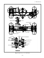
(1) As shown in Fig. 6.9, apply grease to the hub, inner bearing, outer bearing, and cap. Also apply
grease to the oil seal lips.
(2) Set the bearings on the hub, then installed the hub on the knuckle spindle.
(3) Place a washer, then tighten the adjustment nut with a torque of 206 to 235 N-m {21 to 24 kgf-m}
[1823 to 2080 lbf-in.]. Loosen the adjustment nut, then retighten it with a torque of 9.8 N-m {1
kgf-m} [86.7 lbf-in.].
(4) Gently tapping the hub with a mallet, make sure there is no looseness.
(5) Tighten the hub with a mallet, give it a few turns. Then measure the starting torque.
(6) Tapping the hub with a mallet, give it a few turns. Then measure the starting torque.
Starting torque: 1.67 to 1.96 N-m {17 to 20 kgf-cm} [14.8 to 17.4 lbf-in.]
(7) If the starting torque measured is beyond the standard range, replace the washer and adjustment nut.
Then, repeat the steps from (3) to (6) till the standard range is acquired.
(8) Lock the adjustment nut with cotter pin.
OIL SEAL
Fig. 6.9
Pre-Load Adjustment
•
• •
•
•
•
•
OUTER BEARING
INNER BEARING
WASHER
CAP
COTTER PIN
ADJUSTMENT NUT
HUB
Summary of Contents for FB10-7
Page 2: ......
Page 4: ...No SEB 81BBE...
Page 8: ...No SEB 81BBE...
Page 9: ...No SEB 81BBE Fig 1 Overall Dimensions Unit mm in...
Page 10: ...No SEB 81BBE...
Page 28: ...1 BATTERY AND CHARGER 16 NOTE...
Page 30: ...2 MOTORS 18 DRIVE UNIT Fig 2 1 Drive Motor Installation DRIVE AXLE DRIVE MOTOR...
Page 42: ...3 CONTROL SYSTEM 30 Fig 3 2 Inverter Assembly 1 0 to 2 5 ton Trucks...
Page 43: ...31 3 CONTROL SYSTEM Fig 3 3 Inverter Assembly 3 0 to 3 5 ton Trucks...
Page 44: ...3 CONTROL SYSTEM 32 Fig 3 4 Controller Wiring 1 0 to 2 5 ton Trucks...
Page 45: ...33 3 CONTROL SYSTEM Fig 3 5 Controller Wiring 3 0 to 3 5 ton Trucks...
Page 133: ...7 HYDRAULIC SYSTEM 121 Fig 7 27 Remove the oil seal from the front cover...
Page 160: ...8 LOAD HANDLING SYSTEM 148 NOTE...


