- 49 -
3. CONTROL SYSTEM
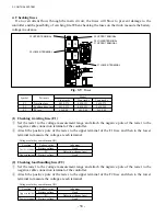
(3) Checking embedded temperature sensor
The U-phase power module (TMDU) and load handling power module (TMP) have temperature
sensors embedded to monitor the temperature of the power module.
When the temperature sensor detects an abnormal temperature of the module, the output current is
restricted.
①
Remove the temperature sensor connectors (THD, THP).
②
Set the tester to a resistance range of 1000
Ω
and measure the resistance between terminals
according to the table given below.
③
Judge whether the module is defective or not, using the measured values of resistance.
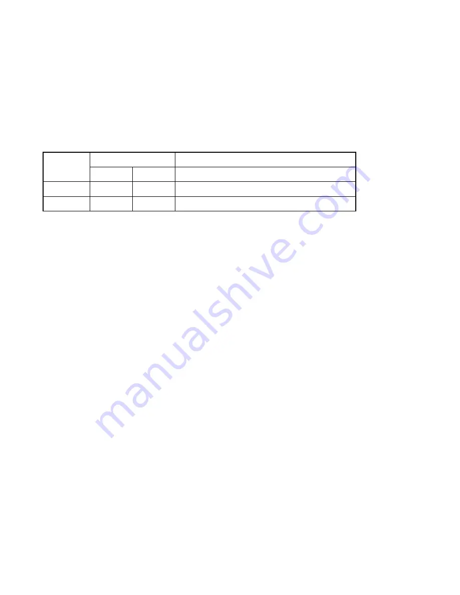
Location
Tester
Normal value
(+)
(–)
Rough guide
THD
THD-1
THD-2
0°C: approx. 66 k
Ω
, 10°C: approx. 40 k
Ω
THP
THP-1
THP-2
20°C: approx. 25 k
Ω
, 30°C: approx. 16 k
Ω
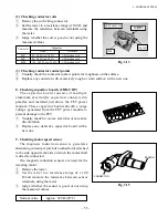
(4) Replacing heat-dissipating insulation sheet
The heat-dissipating insulation sheet is placed between the FET power module and aluminum fin to
provide electrical insulation, while transmitting generated heat to the aluminum fin efficiently.
When replacing the FET power module, make sure to change the insulation sheet with a new one,
too.
The heat-dissipating insulation sheet has a low thermal resistance. It is so thin and fragile that due
caution should be taken when handling. If any damage or cracks are found on it, do not use.
Before installing a new heat-dissipating insulation sheet, make sure the aluminum base, power
module, and insulation sheet are free from metallic powder, cuttings, scores or burrs.
A heat-dissipating insulation sheet which has scores or cracks will lead to a poor insulation
performance, thus causing a shorted FET power module and ground fault.
When installing a new heat-dissipating insulation sheet, align the center of the fitting hole of the FET
module with the center of the hole in the sheet and tighten with care.
Summary of Contents for FB10-7
Page 2: ......
Page 4: ...No SEB 81BBE...
Page 8: ...No SEB 81BBE...
Page 9: ...No SEB 81BBE Fig 1 Overall Dimensions Unit mm in...
Page 10: ...No SEB 81BBE...
Page 28: ...1 BATTERY AND CHARGER 16 NOTE...
Page 30: ...2 MOTORS 18 DRIVE UNIT Fig 2 1 Drive Motor Installation DRIVE AXLE DRIVE MOTOR...
Page 42: ...3 CONTROL SYSTEM 30 Fig 3 2 Inverter Assembly 1 0 to 2 5 ton Trucks...
Page 43: ...31 3 CONTROL SYSTEM Fig 3 3 Inverter Assembly 3 0 to 3 5 ton Trucks...
Page 44: ...3 CONTROL SYSTEM 32 Fig 3 4 Controller Wiring 1 0 to 2 5 ton Trucks...
Page 45: ...33 3 CONTROL SYSTEM Fig 3 5 Controller Wiring 3 0 to 3 5 ton Trucks...
Page 133: ...7 HYDRAULIC SYSTEM 121 Fig 7 27 Remove the oil seal from the front cover...
Page 160: ...8 LOAD HANDLING SYSTEM 148 NOTE...

