5. BRAKE SYSTEM
- 67 -
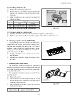
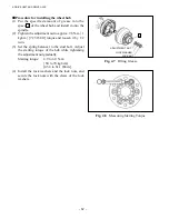
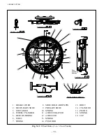
Fig. 5.7
(3) Automatic clearance adjuster
The automatic clearance adjuster automatically
keeps the lining-todrum clearance properly. The
components are as shown in Fig. 5.7. It is put in
action when the brakes are applied while traveling
backward.
■
Operation of the automatic clearance adjuster
When the brake pedal is pressed down in
reverse travel, the secondary shoe is slightly turned
together with the brake drum, and the lever is turned
clockwise around the section
A
shown in Fig. 5.7.
At this step, the section
B
of the lever turns the
adjuster. As the braking force becomes stronger,
the more force is applied to the threaded area of the
adjuster, and the force of the lever cannot turn the
adjuster.
When the brake pedal is released, the brake
shoe returns to the initial position, the lever turns
counterclockwise around the section
A
, and the
section
B
moves downward.
If a tooth of the adjuster is aligned with the section
B
of the lever, the
B
is in mesh with the next tooth
and the clearance is adjusted within the range from
0.25 to 0.4 mm [0.0098 to 0.0157 in.].
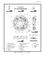
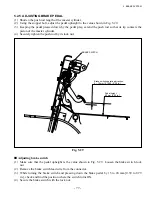
Fig. 5.8
Automatic Clearance Adjuster
LEVER
Expanding direction
CABLE
GUIDE
SPRING
ADJUSTER
Summary of Contents for FB10-7
Page 2: ......
Page 4: ...No SEB 81BBE...
Page 8: ...No SEB 81BBE...
Page 9: ...No SEB 81BBE Fig 1 Overall Dimensions Unit mm in...
Page 10: ...No SEB 81BBE...
Page 28: ...1 BATTERY AND CHARGER 16 NOTE...
Page 30: ...2 MOTORS 18 DRIVE UNIT Fig 2 1 Drive Motor Installation DRIVE AXLE DRIVE MOTOR...
Page 42: ...3 CONTROL SYSTEM 30 Fig 3 2 Inverter Assembly 1 0 to 2 5 ton Trucks...
Page 43: ...31 3 CONTROL SYSTEM Fig 3 3 Inverter Assembly 3 0 to 3 5 ton Trucks...
Page 44: ...3 CONTROL SYSTEM 32 Fig 3 4 Controller Wiring 1 0 to 2 5 ton Trucks...
Page 45: ...33 3 CONTROL SYSTEM Fig 3 5 Controller Wiring 3 0 to 3 5 ton Trucks...
Page 133: ...7 HYDRAULIC SYSTEM 121 Fig 7 27 Remove the oil seal from the front cover...
Page 160: ...8 LOAD HANDLING SYSTEM 148 NOTE...

