


Chapter 1 – Spectra nTier700 VTL Overview
18
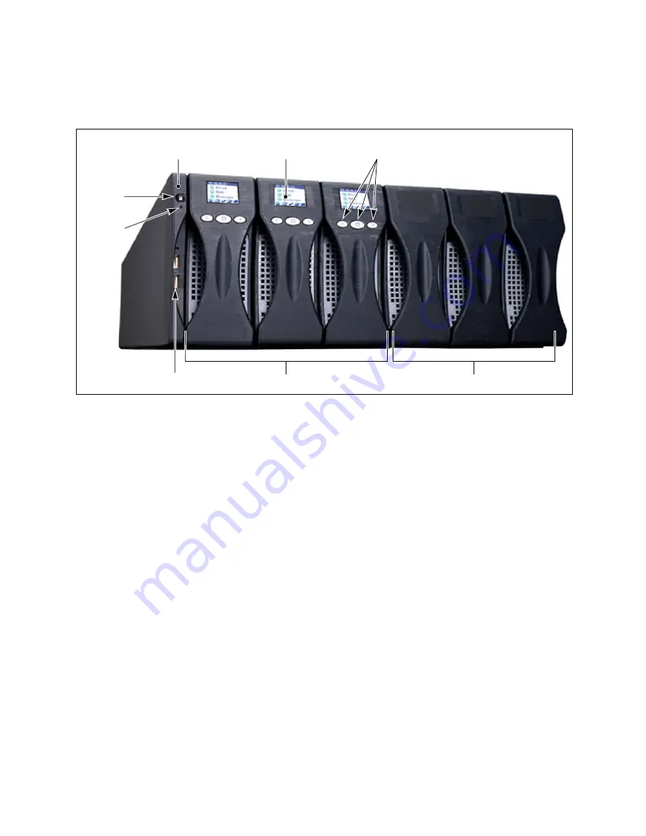
Front Panel
Figure 1-1 shows the front panel components of the Spectra nTier700 VTL.
Chassis management module.
The chassis management module includes the
circuitry for the following:
Power button.
The power button controls the main AC power for the
nTier700 VTL. A blue LED indicates that the power is on.
Standby LED.
The standby LED is amber when power is connected to the
nTier700 VTL, but the power is not turned on. When you press the power
button, this LED turns off.
Universal Serial Bus (USB) ports
. Two USB ports can be used to connect a
USB key to the nTier700 VTL for saving configurations and uploading firmware
packages.
Operator panel LCD screen and buttons.
The operator panel on each
nTier700 VTL blade has a color LCD screen and three buttons for interacting with
the operator panel interface. See
Operator Panel
on page 20 for detailed
information.
RAID 6 blades.
The nTier700 VTL contains up to three sets of high-performance
disk drives mounted in removable enclosures called blades. A minimum of one
blade must be installed in the nTier700 VTL. Each blade contains ten disk drives,
which are preconfigured as a single RAID 6 NAS volume.
o
Figure 1-1
The nTier700 front panel components (nTier700 v3000 shown).
Chassis management
Operator panel
LCD screen
Operator panel
buttons
USB ports (2)
RAID 6 disk blades
module
Power
button
Standby
LED
Blade blanks
Summary of Contents for Spectra nTier700
Page 1: ...Spectra nTier700 Virtual Tape Library Appliance Installation Guide PN 90990038 Revision A...
Page 6: ...Contacting Spectra Logic 6 Notes...
Page 14: ...About This Guide 14 Notes...
Page 24: ...Chapter 1 Spectra nTier700 VTL Overview 24 Notes...
Page 56: ...Chapter 3 Configuring the nTier700 VTL 56 Notes...
Page 74: ...Chapter 4 Using the nTier700 VTL BlueScale Web Interface 74 Notes...


