92
Names and Functions of Parts of the Control Panel
Ch
apt
WIPE:
The current video is replaced by the
new video, using the wipe pattern
selected in the Wipe menu.
DME:
This applies a wipe-like transition,
using the DME effect selected in the
DME Wipe menu.
FM1&2CLIP, FM3&4CLIP,
FM5&6CLIP, FM7&8CLIP:
A
recorded clip is played back together
with the transition. At this point, you
can also carry out a background
transition (wipe or mix (dissolve))
simultaneously together with the clip.
KF (key frame):
Press this button, turning
it on, to enable using the fader lever as
a key frame fader.
b
Key transition selection buttons
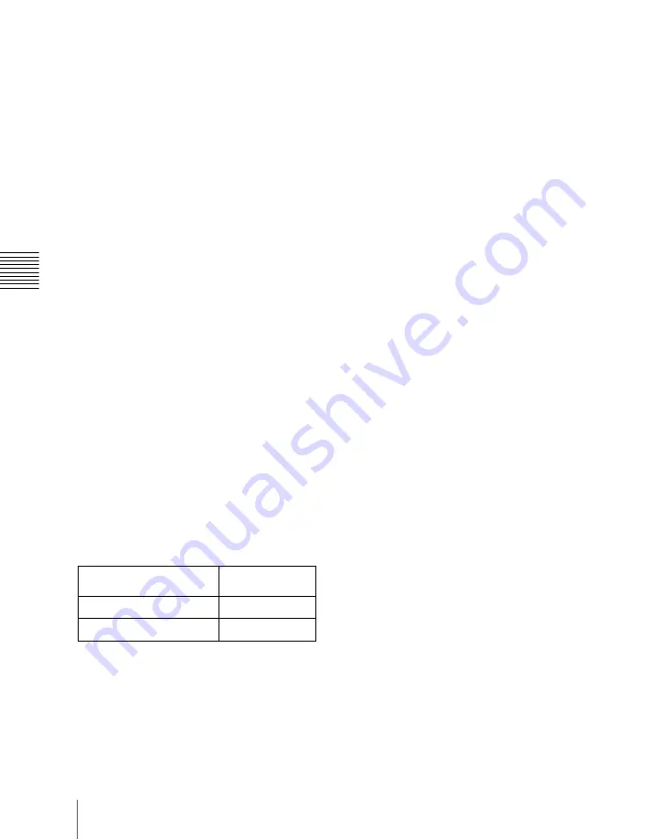
To insert or delete key 1 on the next
transition, hold down the [KEY1] button,
and select the type of transition using the
transition type selection buttons. If the key
is currently not inserted, the transition will
insert it, and if the key is currently inserted,
the transition will delete it. You can use the
[KEY2] button in a similar way.
While these buttons are held down, you can
select a key source with the cross-point
buttons on the key bus.
Pressing one of these buttons twice in rapid
succession changes the state of the
corresponding key bus so that a cross-point
can be selected.
a) The key bus switching button [KEY3] in the cross-
point control block goes off.
b) The key bus switching button [KEY4] in the cross-
point control block goes off.
c
Transition execution section
Fader lever:
Move this vertically to carry
out a transition.
When the [KF] button or a transition
type selection button to which the KF
button function has been assigned is lit,
you can use this as a key frame fader.
When the split fader function is
enabled, by pressing the projection on
the left side of the grip you can release
the lock and separate the two halves of
the fader lever. With the split fader
lever, in a background mix transition,
you can control the background A and
B buses independently.
Transition indicator:
This comprises
multiple LEDs, which show the
progress of the transition.
Transition rate display:
This displays the
transition rate (the time from the
beginning of the transition to its
completion) set for an auto transition,
in frames.
You can set the transition rate using the
numeric keypad control block or menu.
TAKE button:
Pressing this button carries
out an auto transition of the set
transition rate. The transition starts
immediately, and the button lights
amber. When the transition completes,
the button goes off.
d
Wipe direction selection buttons
For details, see “Wipe direction selection
buttons” (page 59).
e
Pattern limit buttons
LIMIT SET:
Move the fader lever to the
position of a particular pattern size, and
stop it there, then press this button to
set the pattern limit range. This button
is enabled when the [PTN LIMIT]
button is off.
PTN (pattern) LIMIT:
When a wipe or
DME wipe is selected, pressing this
Key delegation button
(double press)
Corresponding
key bus
[KEY1]
key 1
a)
[KEY2]
key 2
b)
Summary of Contents for DVS-9000
Page 44: ...44 Setup Chapter 1 DVS 9000 Functions ...
Page 136: ...136 Basic Menu Operations Chapter 2 Menus and Control Panel ...
Page 310: ...310 Wipe Pattern Operations in the Multifunction Flexi Pad Control Block Chapter 5 Wipes ...
Page 440: ...Chapter 9 Color Corrector 440 Color Corrector Functions ...
Page 441: ...Chapter 10 Special Functions Simple P P Software 442 Overview 442 Restrictions on Use 442 ...
Page 446: ...Engineering Setup Menu 484 Diagnostic Menu 488 ...
Page 448: ...Appendix Volume 1 448 Wipe Pattern List Enhanced Wipes 26 27 29 49 300 301 302 303 304 ...
Page 452: ...Appendix Volume 1 452 Wipe Pattern List Random Diamond Dust Wipes 270 271 272 273 274 ...
Page 490: ...DVS 9000 9000SF System SY 3 704 906 11 1 2002 Sony Corporation ...
Page 782: ...Chapter 13 Keyframe Effects 782 Register Operations in the Menus ...
Page 816: ...Chapter 14 Snapshots 816 Snapshot Operations in the Menus ...
Page 838: ...Chapter 15 Utility Shotbox 838 Shotbox Register Editing ...
Page 840: ...Macro Timeline 910 Creating and Editing a Macro Timeline 912 ...
Page 914: ...914 Macro Timeline Chapter 16 Macros ...
Page 945: ...945 SpotLighting Appendix Volume 2 Shape Patterns 1 2 ...
Page 972: ...DVS 9000 9000SF System SY 3 704 906 11 1 2002 Sony Corporation ...
Page 1010: ...Chapter 18 System Setup System 1010 System Maintenance Maintenance Menu ...
Page 1164: ...Chapter 22 DCU Setup DCU 1164 Serial Port Settings Serial Port Assign Menu ...
Page 1190: ...Chapter 25 DIAGNOSIS 1190 Checking the Communications Status ...
Page 1228: ...DVS 9000 9000SF System SY 3 704 906 11 1 2002 Sony Corporation ...


