


24
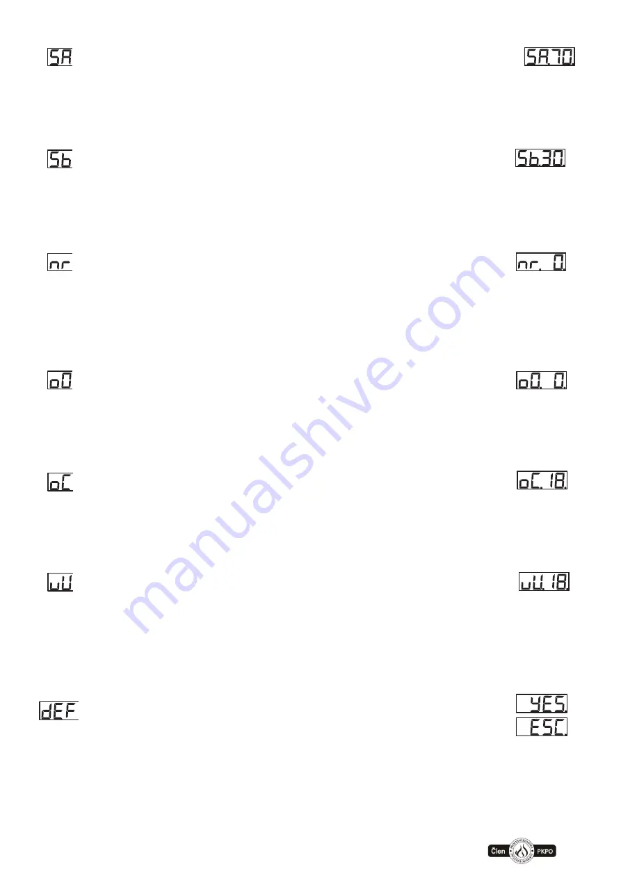
Engine slip – start-up
Range of values: 3–99%
Asynchronous motor slip setting during start-up (the higher the value, the "harder" the
motor and the higher the power and the lower the sensitivity to overload)
Default = 70%
Engine slip – normal run
Range of values: 3–99%
Asynchronous motor slip setting during normal run (the higher the value, the "harder" the
motor and the higher the power and the lower the sensitivity to overload)
Default = 30%
Drive dead band
Range of values: 0–99 impulses of the IRC sensor
Setting of the zone when the drive does not evaluate the overload during start-up and
provides maximum power for pulling out of the stop position. Used when it is necessary to
pull out of the closed position, where blockage can occur due to increased friction.
Default = 0 impulsů
Field of signalisation opened possition
Range of values: 0–99% (percentage of the set movement width)
Setting of the band when the end position opened is reported on the output relay of
terminals X2:31, X2:37. It is possible to shift the message to control other devices.
Default = 2%
Field of signalisation closed possition
Range of values: 0–99% (percentage of the set movement width)
Setting of the band when the end position closed is reported on the output relay of
terminals X2:31, X2:38. It is possible to shift the message to control other devices.
Default = 2%
Maximum motor voltage
Range of values: 5–23 (50 – 230V) po 10V
Setting the maximum output voltage of the motor supplied by the frequency converter. As
the value increases, the "hardness" of the drive increases (the higher the value, the
"harder" the motor and the higher the power and the lower the sensitivity to overload)
Default = 180V
Reset to default parameters
By choosing “YES” will set all parameters to default values
expect parameter “r”, “u”, “U”, “y”, “y”, “h” a “P”
Note: Some of the default parameters can be different against described values above
for some specific types of motors. By resetting parameter “r” (type of mode) will be changed
parameters “r”, “u”, “U”, “y”, “Y-mirror”, “h” a “P” for optimals value for choosen motor. These
parameters is possible to individually adjust but as mentioned above will be reset to default
when changed parametr “r”.
Summary of Contents for FSTronic IRC-FI
Page 36: ...www somati system cz 36 12 2 FSTronic IRC FI CONTROL BOARD DPS ...
Page 38: ...www somati system cz 38 12 4 FSTronic IRC FI CONNECTION OF FIRE DETECTORS ...
Page 39: ...www somati system cz 39 12 5 FSTronic IRC FI Connection aof additional battery module ...
Page 42: ...www somati system cz 42 GridScan PRO SY 2000 FSS GridScan PRO SY 2000 LO ...
Page 43: ...www somati system cz 43 GridScan MINI FSS GridScan MINI PNP NPN ...


