background image

3. Enter the following data in the dialog window:

– Name: 

Select a name for the project.

– Storage location (path):

The default storage location (path), where the new project is to be stored, is displayed 

here.

4. Click OK to confirm.
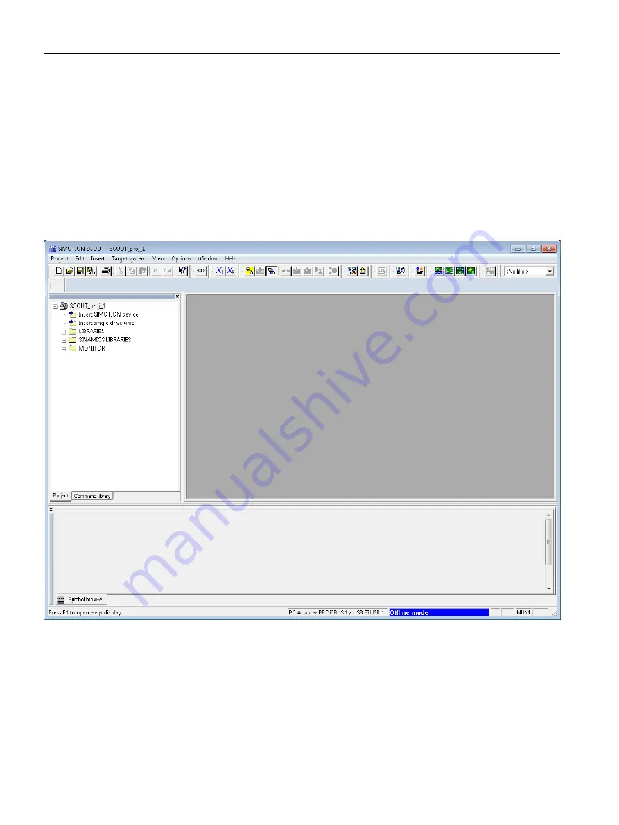
The new project appears in the project navigator with an icon and its full name. The associated 

tree is expanded.

Figure 6-2

Workbench with new project

Configuring/parameterizing
6.3 Managing projects

SIMOTION SCOUT

68

Configuration Manual, 11/2016

Summary of Contents for SIMOTION SCOUT

Page 1: ...nstructions 2 Introduction 3 Installation 4 User interface 5 Configuring parameterizing 6 Target system 7 Upgrading and project updates 8 Diagnostics 9 Service with SIMOTON SCOUT 10 Siemens SIMOTION Diagnostics 11 Configuring a further connection such as HMI 12 Product combinations 13 Technical specifications 14 Appendix A ...

Page 2: ...lified personnel are those who based on their training and experience are capable of identifying risks and avoiding potential hazards when working with these products systems Proper use of Siemens products Note the following WARNING Siemens products may only be used for the applications described in the catalog and in the relevant technical documentation If products and components from other manuf...

Page 3: ...IMOTION SCOUT 19 3 4 2 Motion Control Chart MCC 21 3 4 3 Ladder Logic Function Block Diagram LAD FBD 22 3 4 4 Structured Text ST 23 3 5 CamEdit cam editor 24 3 6 CamTool options package 24 3 7 Technology packages and technology objects 25 3 8 CLib Studio option package 26 4 Installation 27 4 1 SCOUT and SCOUT Standalone system requirements 27 4 2 Installing SIMOTION SCOUT 27 4 2 1 Installing SIMOT...

Page 4: ...lp 60 5 10 3 Getting Started with SIMOTION SCOUT 61 5 10 4 Error remedy 62 5 11 Adding add ons to the workbench 63 6 Configuring parameterizing 65 6 1 Configuration overview 65 6 2 SIMOTION SCOUT basic settings 65 6 3 Managing projects 66 6 3 1 SIMOTION SCOUT project 66 6 3 2 Creating a new project 67 6 3 3 Open project 70 6 3 4 Saving and compiling 71 6 3 5 Performing a consistency check 72 6 3 6...

Page 5: ...ION application 110 6 6 1 Using tags 110 6 6 2 Using MCC 113 6 6 2 1 Overview 113 6 6 2 2 Creating the MCC unit 114 6 6 2 3 Creating an MCC chart 115 6 6 2 4 Using MCC command blocks 117 6 6 2 5 Backing up the MCC program 119 6 6 3 Using LAD FBD 120 6 6 3 1 Overview 120 6 6 3 2 Create LAD FBD unit 121 6 6 3 3 Create LAD FBD program 122 6 6 3 4 Using the LAD FBD toolbar 124 6 6 3 5 Backing up the L...

Page 6: ...Setting the time of day 161 7 6 Loading data to the target system 161 7 7 Archive project data to memory card 162 7 8 Loading to the file system 162 8 Upgrading and project updates 163 8 1 General information 163 8 2 Upgrading and changing platforms for a SIMOTION device 163 8 2 1 Changing a SIMOTION device and subsequent TP upgrade within a platform 163 8 2 2 Changing the SIMOTION platform 165 8 ...

Page 7: ...Project was created in Version V4 1 V4 2 V4 3 V4 4 199 10 3 Project V4 1 V4 2 V4 3 V4 4 has been edited with SCOUT V4 5 200 10 4 Introduction of versioning with standard library and software components 201 11 Siemens SIMOTION Diagnostics 203 12 Configuring a further connection such as HMI 205 12 1 Rules for arranging modules in the HW Config 205 12 2 Routing 206 12 3 HMI Human Machine Interface co...

Page 8: ...g system 222 14 Technical specifications 225 14 1 Quantity framework 225 14 2 Memory requirement 225 A Appendix 227 A 1 Scripts for SIMOTION 227 A 2 Creating an example program for axis positioning in SIMOTION SCOUT 227 Index 239 Table of contents SIMOTION SCOUT 8 Configuration Manual 11 2016 ...

Page 9: ...ew of the SIMOTION SCOUT Workbench It also provides notes concerning the language setting and the use of online help Configuring parameterizing This chapter describes the basic steps for operating SIMOTION SCOUT Target system This chapter contains information on controlling the target system You also learn how you can control the operating state with SIMOTION SCOUT and how you can upload data to t...

Page 10: ...entation packages The following documentation packages are available for SIMOTION V4 5 SIMOTION Engineering System Handling SIMOTION System and Function Descriptions SIMOTION Service and Diagnostics SIMOTION IT SIMOTION Programming SIMOTION Programming References SIMOTION C SIMOTION P SIMOTION D SIMOTION Supplementary Documentation 1 4 Hotline and Internet addresses SIMOTION at a glance We have co...

Page 11: ...try siemens com My ww en documentation Training Click the following link for information on SITRAIN Siemens training courses for automation products systems and solutions http www siemens com sitrain FAQs Frequently Asked Questions can be found in SIMOTION Utilities Applications which are included in the scope of delivery of SIMOTION SCOUT and in the Service Support pages in Product Support https ...

Page 12: ...Preface 1 4 Hotline and Internet addresses SIMOTION SCOUT 12 Configuration Manual 11 2016 ...

Page 13: ... instructions given in the hardware documentation Consider the residual risks for the risk evaluation WARNING Danger to life caused by machine malfunctions caused by incorrect or changed parameterization Incorrect or changed parameterization can cause malfunctions on machines that can result in injuries or death Protect the parameterization parameter assignments against unauthorized access Respond...

Page 14: ... to make them more secure Siemens strongly recommends to apply product updates as soon as available and to always use the latest product versions Use of product versions that are no longer supported and failure to apply latest updates may increase customer s exposure to cyber threats To stay informed about product updates subscribe to the Siemens Industrial Security RSS Feed under http www siemens...

Page 15: ...risk of infection e g via viruses or malware Incorrect parameter assignment can cause machines to malfunction which can lead to injuries or death Protect the files on removable storage media against harmful software through appropriate protective measures e g virus scanners Fundamental safety instructions 2 3 Danger to life due to software manipulation when using removable storage media SIMOTION S...

Page 16: ...Fundamental safety instructions 2 3 Danger to life due to software manipulation when using removable storage media SIMOTION SCOUT 16 Configuration Manual 11 2016 ...

Page 17: ... use for the necessary engineering steps are required for this The SIMOTION SCOUT Engineering System is the environment for the uniform automation of production machines with SIMOTION and integrates into the SIMATIC environment in accordance with TIA Totally Integrated Automation SIMOTION SCOUT provides a uniform function oriented view for your automation task and at the same time it is very easy ...

Page 18: ...eated by parameterizing the required components and networks 3 3 SIMOTION hardware platforms To meet the complex requirements of machine construction SIMOTION offers three hardware variants with different performance packaging formats and expandability options The basic system characteristics like the engineering are identical SIMOTION D Drive based SIMOTION D is a compact drive based version of S...

Page 19: ...lowing programming languages are available in SIMOTION SCOUT Motion Control Chart MCC Graphical programming as a flow chart In particular for sequential tasks with a high level of motion control functionality Ladder Logic Function Block Diagram LAD FBD Graphical Programming as Ladder Logic Function Block Diagram supplemented by Motion Control Functions via PLCopen Function Blocks In particular for...

Page 20: ... program code of the POUs Any POUs not specified in the interface section can only be used within the source Note Source concept The source concept with encapsulation of code and data allows you to structure applications For example the functionality of an entire machine module with a defined external interface can be implemented in a single source Tasks Programs are processed in tasks A task is a...

Page 21: ...s a selection of the most important SIMOTION functions are available in tool bars They are grouped according to function and are automatically inserted in the flow diagram at the marked point by means of a click A click on the individual elements opens specific dialogs for parameterization Obviously you can also add your own comments for the further documentation of the process sequence Functions ...

Page 22: ... LAD FBD A source can contain several LAD and FBD blocks Only one POU can be implemented in an LAD or FBD block LAD FBD also include commands for SIMOTION system control using standard logic functions These commands are added from the command library Motion Control tasks are preferably programmed with PLCopen blocks Blocks which have been programmed in other SIMOTION languages can be called User f...

Page 23: ...e level but are instead called in programs Note As of SIMOTION SCOUT V4 5 ST also supports object oriented programming Further information can be found in the SIMOTION SCOUT online help and in the SIMOTION ST Structured Text Programming and Operating Manual Performance features Motion Control PLC and technology functions in a single language Well structured programs with comment capability Powerfu...

Page 24: ...rt and edit cams Cams can be inserted in a SIMOTION SCOUT project using the SIMOTION CamTool You can also edit a cam created with CamEdit using CamTool Cams can also be imported from a text file or read from a SIMOTION device Customize display of the cam in CamTool In SIMOTION CamTool you can show and hide diagrams change display parameters of the axes and diagrams and adjust the lines and fonts Y...

Page 25: ...ion technology Path interpolation generates the traversing profile for the path calculates the path interpolation points in the interpolation cycle and uses the kinematic transformation to derive the axis setpoints for the interpolation cycle points CAM_EXT technology package The CAM_EXT technology package also contains objects for preparing technological data at the system level e g addition obje...

Page 26: ...ontrol TO Axis Electric Hydraulic TO External Encoder Function Manual SIMOTION Motion Control Synchronous Operation TO TO Cam Function Manual SIMOTION Motion Control Supplementary Technology Objects Function Manual SIMOTION Motion Control Output Cams and Measuring Inputs Function Manual SIMOTION Motion Control TO Path Object Function Manual SIMOTION Motion Control Basic Functions for Modular Machi...

Page 27: ... is integrated as of SIMOTION SCOUT V4 0 4 2 Installing SIMOTION SCOUT 4 2 1 Installing SIMOTION SCOUT SIMOTION SCOUT is available as software packages with full license and upgrade license Requirements SIMATIC STEP 7 is installed You are logged on to the operating system with administrator rights Note Read the readme file and the important information on the SIMOTION SCOUT Add Ons DVD contained i...

Page 28: ...ant information on the Add On CD supplied with SCOUT To install SIMOTION SCOUT Standalone 1 Insert DVD 1 with SIMOTION SCOUT Standalone into the CD ROM drive 2 Start Windows Explorer and select the CD ROM drive 3 Open the root directory on the DVD 4 Double click Setup exe 5 Now follow the instructions in the installation program The installation program prompts you to insert or connect the supplie...

Page 29: ...r the relevant SSP contain detailed information regarding installation 4 3 Uninstalling SIMOTION SCOUT Requirements You are logged on to the operating system with administrator rights Note Note that the SIMATIC STEP 7 software must be uninstalled separately To uninstall SIMOTION SCOUT from the hard disk 1 Open the Windows Control Panel Go to the Programs and Functions page Windows 7 2 Select SIMOT...

Page 30: ...ndow 4 Mark the license key and drag this with drag and drop to the target drive 5 Exit the Automation License Manager 6 Remove the data medium containing the authorization Note Information on operating the Automation License Manager and transferring the license key can be found in the online help for the Automation License Manager The authorization for SIMOTION SCOUT and SIMOTION SCOUT Standalone...

Page 31: ...t interrupt the upgrade while it is in progress Interrupting this process can lead to the license key being lost 7 Now transfer the new floating license onto the hard disk drive To do this follow the same procedure as before Via License key Transfer in the menu 8 After the transfer has completed successfully remove the automation data medium 9 Exit the Automation License Manager SIMOTION SCOUT can...

Page 32: ...Installation 4 4 Licenses SIMOTION SCOUT 32 Configuration Manual 11 2016 ...

Page 33: ...em The workbench is the navigation center of the individual engineering steps and offers a uniform and integrated view of all data and programs The following figure shows an example of the Workbench components 2 1 7 6 5 4 3 Menu bar Tool bars Working area Project navigator Snap in Tab Detail view SIMOTION SCOUT Configuration Manual 11 2016 33 ...

Page 34: ...SCOUT Workbench Snap ins provide functions for processing SIMOTION SCOUT projects and are displayed as a work window in the working area of the workbench Several Snap ins can be opened Open Snap ins are displayed in the working area as tabs The active Snap in is visible in the foreground The following Snap ins are available Program editors Wizards for the configuration of technology objects Device...

Page 35: ...ION SCOUT twice 5 2 SIMOTION SCOUT working area The workbench displays all of the Snap in work windows in the working area Each Snap in provides its own work window You can open multiple instances of these windows You can for example open several programs at the same time for editing For further information refer to the online help The following table provides an overview of the active functions i...

Page 36: ...oreground Click the relevant tab Select the appropriate entry in the Window menu To close a window proceed as follows Configuration dialogs Click Close Editors for MCC ST and LAD FBD Click the X button in the top right hand corner Configuration dialogs and editors can also be closed with Ctrl F4 5 3 SIMOTION SCOUT project navigator 5 3 1 Using the project navigator The project navigator in the SIM...

Page 37: ...lement Insert single drive unit Note You can insert a standalone drive e g SINAMICS S120 with the Insert single drive unit element in the project navigator It is commissioned using wizards in the working area of the workbench that contains the Starter functionality Elements within a SIMOTION device Create the following elements within a SIMOTION device directly in the project navigator Technology ...

Page 38: ...nables you to insert a standalone drive e g SINAMICS S120 The STARTER functionality in SCOUT is responsible for commissioning the drive concerned Inserting elements within a SIMOTION device To insert technology objects source files or watch tables 1 Open the SIMOTION device under which the element is to be created 2 Select the relevant folder e g AXES PROGRAMS 3 Select the desired function e g Ins...

Page 39: ...onfig of a SIMOTION device To call up the hardware configuration of a previously inserted SIMOTION device In the project navigator double click the SIMOTION device whose hardware configuration you want to open or Select the desired SIMOTION device in the project navigator open the context menu and click Open HW configuration 5 3 3 Inserting a folder Inserting a folder in the project navigator For ...

Page 40: ...ant to rename in the project navigator 2 Open the context menu and select Rename 3 Confirm the warning message 4 Enter a new name and confirm the input by pressing the Enter key NOTICE Damage resulting from errors in references to the axis Changing a name can have far reaching consequences References to the axis particularly in programs are lost This can cause runtime errors in the program For thi...

Page 41: ...erdependencies are taken into account Figure 5 1 Axis configuration wizard window for drive assignment 5 4 SIMOTION SCOUT menus SIMOTION SCOUT menus are subdivided into static and dynamic menus Static menu Static menus are primarily used to control the workbench or a project and are permanently displayed User interface 5 4 SIMOTION SCOUT menus SIMOTION SCOUT Configuration Manual 11 2016 41 ...

Page 42: ...ynamic menu Dynamic menus are provided by Snap ins and are added to the static menu The menu active in the working area is always displayed User interface 5 4 SIMOTION SCOUT menus SIMOTION SCOUT 42 Configuration Manual 11 2016 ...

Page 43: ...visible only when project has been loaded Insert Static menu visible only when project has been loaded Target system Static menu always visible View Static menu always visible Options Static menu always visible Window Static menu always visible Help Static menu always visible User interface 5 4 SIMOTION SCOUT menus SIMOTION SCOUT Configuration Manual 11 2016 43 ...

Page 44: ...second position on the menu bar between Project and Edit MCC chart LAD FBD source LAD FBD program 5 5 SIMOTION SCOUT menu items You can use the shortcuts listed in the table to call the menu items available in SIMOTION SCOUT Table 5 3 Menu items in SIMOTION SCOUT Shortcuts Menu item Reaction Project Ctrl N New Creates a new project Ctrl O Open Opens a project Ctrl S Save Saves a project Ctrl Alt K...

Page 45: ... in the project Opens the Find window Ctrl Shift G Replace in the project Opens the Find and Replace window CTRL H Replace Opens the Replace window CTRL J Display next position Shortcuts Menu item Reaction Target system Ctrl L Download target device Downloads to individual target device Ctrl D Is possible only online Device diagnostics Opens device diagnostics Ctrl I Is possible only online Contro...

Page 46: ...space Automatic completion Ctrl F2 Sets and deletes bookmarks Ctrl F4 ST source file Close Closes the ST source file Ctrl F7 ST source file Program sta tus on off Switches the program status function on or off Ctrl Shift F2 Deletes all bookmarks in the ST source file Ctrl Shift F3 Arranges windows tile horizontally Ctrl Shift F5 Arranges windows tile vertically Ctrl Shift F8 Formats the selected a...

Page 47: ...e current ST source file Ctrl MINUS numer ic keypad Decreases the font size in the current ST source file Ctrl DIV numeric keypad Resets the font size in the current ST source file to 100 Alt Shift arrow key Selects text by column Alt Shift L Changes selected text to upper case Alt Shift U Changes selected text to lower case Shortcuts Menu item Reaction MCC Ctrl F4 Close Closes the MCC source Alt ...

Page 48: ... FBD Add element Add coil Add element assign ment or jump Adds a coil Adds an assignment or a jump Shift F8 for LAD Shift F8 for FBD Insert element Insert Open branch element Insert binary in put Inserts an Open branch Inserts a binary input Shift F9 for LAD Shift F9 for FBD Insert element Insert Close branch element Invert binary in put Inserts a Close branch Inverts the binary input Shift Alt F9...

Page 49: ...e desktop Ctrl F12 Minimize maximize detail view in relation to the whole desktop Project navigator Click with left mouse button Selects the tree object at the cursor position the detail view displays the associated details Double click with left mouse button Selects the tree object at the cursor position the detail view displays the associated details the associated Snap in opens Click with right...

Page 50: ... To call the desired function of the tree element via context menus proceed as follows 1 Select the appropriate element in the project navigator 2 Open the context menu with a right click 3 Left click the appropriate command to select it Figure 5 4 Context menu for SIMOTION device User interface 5 7 SIMOTION SCOUT using the context menus SIMOTION SCOUT 50 Configuration Manual 11 2016 ...

Page 51: ...are determined by the project mode offline online and the active Snap ins Figure 5 5 Example of detail view Each tab is opened just once i e The active tab shows the details of the selected element The contents of the tab change when you select a different element You can maximize or minimize each tab with Ctrl F12 5 8 2 Using the symbol browser The symbol browser is a tab in the detail view The s...

Page 52: ...t the address list is available in the SIMOTION SCOUT online help 5 8 4 Watch table With the symbol browser you can view the variables belonging to one object in your project with the program status you can view the variables belonging to a selected monitoring area in the program With watch tables in contrast you can monitor selected variables from different sources as a group e g program sources ...

Page 53: ...ou can monitor the variable contents Using several watch tables Watchtabelle_temp If you want to monitor several watch tables simultaneously watch tables of different objects create a temporary watch table The temporary watch table has the following properties It is always called Watchtabelle_temp It does not save the contents when it is closed It can be filled using drag and drop It does not supp...

Page 54: ...ing of the SIMOTION SCOUT SIMOTION SCOUT uses the language default setting in the SIMATIC Manager You can make changes to this setting in the SIMATIC Manager via the Options Settings Language menu German English French and Italian languages are currently available in SIMOTION SCOUT If a different language is set in the SIMATIC Manager SIMOTION SCOUT uses the English setting Note Only those languag...

Page 55: ...or the full text search on the Search tab 2 Navigation area In the navigation area you can navigate through the help open the index or search through the entire help Click the Contents Index or Search tab to navigate through the help Click the in front of a book to open the table of contents Click a book or help page to display its contents in the contents area User interface 5 10 SIMOTION SCOUT u...

Page 56: ...his link bar displays further information for the selected help page The link bar contains the fol lowing entries In Section Links to headers of the displayed topic Manuals Links to handling instructions Examples Links to examples Fundamentals Links to background information such as definitions or details History List of the most recently opened help pages Options Link to the start page Forwards a...

Page 57: ...e dialog opens Context sensitive help Shift F1 Press Shift F1 or Click the button in the menu bar or In the menu select Help Context help The mouse pointer changes to a question mark Then click with the changed mouse cursor on the dialog the parameter the input field or the menu item The context sensitive help for the selected entry opens User interface 5 10 SIMOTION SCOUT using help SIMOTION SCOU...

Page 58: ...ject navigator The general help for the project naviga tor opens Help for the technology ob ject only SIMOTION Press Shift F1 Then click with the question mark on a technology object in the project navigator The help for this technology object opens User interface 5 10 SIMOTION SCOUT using help SIMOTION SCOUT 58 Configuration Manual 11 2016 ...

Page 59: ... project navigator select the SI MOTION device or the technology ob ject The system variables of the element are displayed in the symbol browser Press Shift F1 Then click with the question mark on the system variable in the symbol browser The associated help opens Help for alarms Press Shift F1 Then click with the question mark on the alarm shown on the Alarms tab The help for the drive alarm or t...

Page 60: ...arameter in the expert list The help opens Help for the LAD FBD editor only SIMOTION Declaration area Press Shift F1 Then click with the question mark on a tab in the declara tion area of the LAD FBD editor The help opens Editor area Press Shift F1 Then click with the question mark on an element in the ed itor area of the LAD FBD editor The help opens 5 10 2 Searching in the online help You can ca...

Page 61: ...tle Position or Order With many search results it is better to sort them by position so hits are grouped together by subject matter 4 Double click the desired subject to display the Help page The found terms are highlighted on the page Note If the terms are not highlighted of if you want to turn the highlighting off click the Options button select Activate deactivate search term highlighting in th...

Page 62: ...TION SCOUT online help To deactivate the default setting that automatically opens the online help when you launch SIMOTION SCOUT 1 In the menu bar select Options Settings 2 Click the Workbench tab 3 Deactivate the Display Getting started at start checkbox 4 Click OK 5 10 4 Error remedy In the online help you can find detailed information about error messages appearing in the detail view of the SIM...

Page 63: ...d ons are added to the workbench and are displayed as fully integrated Menus and toolbars appear at the appropriate position in the workbench After installation of add ons the menus are visible and the toolbars are active The working windows appear in the working area of the workbench and have tabs The detail view of the workbench shows details about the currently active add on If the associated d...

Page 64: ...User interface 5 11 Adding add ons to the workbench SIMOTION SCOUT 64 Configuration Manual 11 2016 ...

Page 65: ...ams Commission and optimize drives and axes Test the system and utilize the diagnostic options SIMOTION SCOUT provides the workbench to enable you to perform these steps easily and efficiently 6 2 SIMOTION SCOUT basic settings In SIMOTION SCOUT you have the possibility of predefining various basic settings via the Options Settings menu Detailed information on the individual tabs and settings is pr...

Page 66: ...ect is therefore the sum of all data programs settings etc The project encompasses all of the SIMOTION devices drives etc that belong to a machine The axes external encoders path objects cams technology and programs are assigned hierarchically to the respective devices This hierarchical structure is displayed in the project navigator Configuring parameterizing 6 3 Managing projects SIMOTION SCOUT ...

Page 67: ...workbench menu bar select Project New The New Project window opens Note SIMOTION SCOUT creates a directory with the selected name All files relevant to the project are stored in this directory Directory names and file names are shortened to 8 characters If you assign longer names they are displayed in SIMOTION SCOUT However these names are only managed with 8 characters in the Explorer Special cha...

Page 68: ...ion path where the new project is to be stored is displayed here 4 Click OK to confirm The new project appears in the project navigator with an icon and its full name The associated tree is expanded Figure 6 2 Workbench with new project Configuring parameterizing 6 3 Managing projects SIMOTION SCOUT 68 Configuration Manual 11 2016 ...

Page 69: ...ure 6 3 Insert SIMOTION device Insert single drive unit element Double click this icon to insert and commission a standalone drive e g MM4 Basic Although this drive cannot be linked to or configured in the master system of the project using a PROFIBUS DP connection it appears in the project navigator within the project Folder labeled LIBRARIES Folder labeled MONITORING Configuring parameterizing 6...

Page 70: ...ject that was created in an older version a message appears asking whether the project should be converted to the newer version This function is available since SIMOTION SCOUT Version V3 1 Note The Save as function saves all previously made changes with a new name as of V4 4 Figure 6 4 Opening a project stored on the hard disk Note The workbench displays one project at a time If you want to displa...

Page 71: ...d recompile all All sources of the entire project are recompiled with this command The Save and recompile all command is suitable if you are entirely sure that all the old data from older SCOUT versions has been removed and should be replaced with new compilation results The command incorporates the following steps Project wide deletion of all compilation results Recompilation of all objects Use t...

Page 72: ...een compiled without errors To compile all programs automatically before a download and to check the consistency the Compile all programs before loading and Check consistency before loading checkboxes must be activated via Options Settings on the Download tab For further information please refer to the online help for SIMOTION SCOUT 6 3 6 Archiving and backing up projects on memory cards Procedure...

Page 73: ...unction Remove data from the archive to reduce the file size Divide the archive into packets so that you can create several ZIP files that are combined again when dearchiving For further information please refer to the online help for SIMOTION SCOUT Additional references Detailed information on loading data to the target device can be found in the SIMOTION SCOUT Basic Functions Function Manual 6 3...

Page 74: ... file is displayed in this field so that you only have to perform the following steps when you want to import another file To select the import file 1 Click Browse to the right of the text field A window opens 2 Select the XML file that is to be imported Only a technology object that is completely available can be imported Always select the XML file which has the name of the previously exported te...

Page 75: ...Local search You can search locally for a specific text in the various editors and the declaration tables To start searching locally open the search function with the Ctrl F shortcut key while the current focus is on an editor e g MCC or the editor window for global and unit global declarations and connections The SIMOTION MCC Motion Control Chart Programming and Operating Manual contains further ...

Page 76: ...arious parts of a project or view them in the print preview in order to for example document settings data etc The part to be printed depends on the element selected in the project navigator or the window active in the working area An element is selected in the project navigator or a window is active in the working area The data of the associated technology object MCC chart etc is printed The deta...

Page 77: ...le click the Insert SIMOTION device entry below the name of your project in the project navigator The following dialog opens Figure 6 6 Insert SIMOTION device Select the device platform you are working with at Device The characteristics of the relevant platform then appear under Device characteristic Configuring parameterizing 6 4 Configuring devices SIMOTION SCOUT Configuration Manual 11 2016 77 ...

Page 78: ...f the drives In addition you also specify which parameters the SIMOTION system should use e g Configuration of the SIMOTION device Configuration of the PROFIBUS PROFINET Assignment of the hardware to PROFIBUS PROFINET The following sections explain how to use the HW Config tool How to insert objects from the hardware catalog How to edit objects How to replace or delete objects 6 4 1 1 Starting HW ...

Page 79: ... edit them here In the lower half you can see detailed information about the selected objects Figure 6 7 HW Config with opened hardware catalog and the CPU previously inserted in the module 6 4 1 3 HW Config Opening the hardware catalog You can open the hardware catalog in the following ways Select the Insert Insert object menu Select the View Catalog menu For further information see Section Inser...

Page 80: ...g the interfaces opens Note With SIMOTION D the PROFIBUS subnet PROFIBUS Integrated DP master system is created and configured automatically The user may neither configure nor select it Figure 6 8 Hardware configuration of a D4x5 Detailed information on the configuration of the SIMOTION device is contained in the corresponding documentation for the SIMOTION devices 6 4 2 Selecting technology packa...

Page 81: ...y Packages command in the context menu Figure 6 9 Selecting technology packages Note Device diagnostics can provide information on which technology package product version has been loaded to a CPU Loading technology packages to the target device Technology packages are only loaded to the target device if no technology package has been loaded so far If a technology package version changes the techn...

Page 82: ...ivers on the PG PC Connect the interface card to the interface of the SIMOTION device indicated below using a suitable cable Table 6 1 Interface assignment for SIMOTION devices SIMOTION device Interface As supplied SIMOTION C230 2 C240 X8 DP1 X9 DP2 MPI PROFIBUS address 2 baud rate 1 5 Mbit s PROFIBUS address 2 baud rate 1 5 Mbit s X7 Ethernet IP address 169 254 11 22 Subnet 255 255 0 0 SIMOTION C...

Page 83: ...Ethernet Supplied without IP address and subnet IP address 169 254 11 22 Subnet mask 255 255 0 0 Supplied without IP address and subnet SIMOTION D4x5 2 DP PN X126 DP X136 DP MPI PROFIBUS address 2 baud rate 1 5 Mbit s PROFIBUS address 2 baud rate 1 5 Mbit s X127 P1 PN IE Ethernet X130 P1 PN IE NET Ethernet IP address 169 254 11 22 Subnet mask 255 255 0 0 Supplied without IP address and subnet X150...

Page 84: ...face with 2 ports Supplied without IP address and subnet 6 4 3 2 Set PG PC interface Setting interfaces Proceed as follows 1 Start SIMOTION SCOUT 2 Select the Options Set PG PC interface menu The Set PG PC Interface window opens Figure 6 10 Set PG PC interface example 3 Select the access point of the application Configuring parameterizing 6 4 Configuring devices SIMOTION SCOUT 84 Configuration Man...

Page 85: ...ninstall 4 Click Close 5 Select the interface to be used in the Used interface parameterization field The list of the used interface parameterization will be taken from SIMATIC STEP 7 With the PC Adapter Auto setting the interface to which the PG PC is connected is examined This function automatically determines the current parameterization of the respective interface Detailed information on the i...

Page 86: ...ty of manufacturers Configuration commissioning and troubleshooting can be carried out from any side This results in user defined communication relationships that are very versatile simple to implement and easy to change The high speed cyclic exchange of data with field devices distributed I O is carried out via the PROFIBUS DP protocol Expansion of the protocol to include isochronous mode also in...

Page 87: ...e connection to a higher level automation system For the connection of HMI devices For the connection to the SCOUT engineering system 6 4 3 5 Ethernet communication SIMOTION devices can also be connected to a PG PC via Industrial Ethernet Industrial Ethernet is a communication network with a transmission rate of 1 Gbit s For additional information refer to the Manual SIMATIC NET Industrial Twisted...

Page 88: ...and Hardware Installation Manual SIMOTION D410 Commissioning Manual SIMOTION D410 2 Commissioning and Hardware Installation Manual SIMOTION P320 4 E P320 4 S Commissioning and Hardware Installation Manual SIMOTION C Operating Instructions SIMOTION Communication System Manual and the SIMOTION SCOUT online help 6 4 4 Inserting a drive 6 4 4 1 Drives with SIMOTION Note the following Drives must be di...

Page 89: ...the project via the hardware configuration The SIMOTION device requires only the actual values from the encoder at the input and issues the setpoints at the analog output The drives must be configured assigned parameters and commissioned directly on the corresponding device With SIMOTION D drives on SINAMICS Integrated are not inserted via the HW Config For more detailed information see the D Comm...

Page 90: ...rive 6 4 4 3 Inserting a SINAMICS drive on PROFINET IO Initial situation The SIMOTION device is created in SIMOTION SCOUT A PROFINET IO system and an Ethernet subnet are configured Proceed as follows 1 Open the HW Config of the SIMOTION device 2 Open the PROFINET IO Drives SINAMICS folder in the hardware catalog Configuring parameterizing 6 4 Configuring devices SIMOTION SCOUT 90 Configuration Man...

Page 91: ... Communications System Manual Inserting and Configuring SINAMICS S120 section as well as at the FAQ SIMOTION SINAMICS Distributed synchronous operation and isochronous mode via PROFINET IRT 6 4 4 4 Commissioning the drives Drives that can be commissioned with SIMOTION SCOUT You can use SIMOTION SCOUT to assign parameters to the following drives SINAMICS MICROMASTER COMBIMASTER 411 Configuring para...

Page 92: ...IMOTION SCOUT or DRIVE ES Basic or STARTER SIMODRIVE 611U PROFIBUS DP or analog interface With SIMOCOM U or DRIVE ES Basic MASTERDRIVES MC VC PROFIBUS DP or analog interface With SIMOVIS or DRIVE ES Basic SIMODRIVE POSMO CA CD SI PROFIBUS DP With SIMOCOM U or DRIVE ES Basic Third party drives Analog interface or PROFIBUS DP accord ing to PROFIdrive profile V3 02 With commissioning tool supplied by...

Page 93: ...Save and compile in the HW Config and then close HW Config 10 Open the structure tree of the SIMOTION device in the project navigator 11 Open the structure tree of the drive SINAMICS or SINAMICS_Integrated in the project navigator 12 Double click Configure drive unit The Configuration Option Module window opens 13 Run through the drive wizard The STARTER functionality now starts in SIMOTION SCOUT ...

Page 94: ...oning and Hardware Installation Manuals Infeed without DRIVE CLiQ interface If you are using an infeed without a DRIVE CLiQ interface e g a Smart Line Module you must wire the ready signal of the infeed via terminals The following section describes the procedure Configure the infeed without a DRIVE CLiQ interface Interconnecting the ready signal of the infeed An infeed without DRIVE CLiQ interface...

Page 95: ...ration below the drive Figure 6 14 Configuring a drive 2 Click in the working area on the Configure DDS button with the yellow background Figure 6 15 Configuring DDS The drive wizard opens 3 Click Next in the drive wizard until you reach the dialog Configuration SINAMICS_Integrated BICO power unit 4 In the input field p0864 select the digital input e g DI 0 to which the ready signal of the infeed ...

Page 96: ...afety instructions are observed The non observance can cause injury to persons or damage to material The function is released exclusively for commissioning diagnostic and service purposes The function should generally only be used by authorized technicians The safety shutdowns from the higher level control have no effect The Stop with preconfigured braking ramp function is not guaranteed in all op...

Page 97: ...trol area in order to test the motor speed specified at n 2 Click the button to show the diagnostics area in order to display and evaluate the defined parameters You can determine the status of the required enables by clicking the Diagnostics button 3 In the selection list select the drive that you want to control or monitor using the PG PC SINAMICS_Integrated_1 SERVO_03 in the example 4 Specify t...

Page 98: ...an infeed without a DRIVE CLiQ interface you must interconnect the Infeed operation signal drive parameter p0864 yourself In this case the dialog does not contain any fields for selecting infeed If the signal of the Closed loop control operation infeed is already BICO interconnected with the drive the infeed is specified permanently No selection is possible in the dialog the fields are grayed out ...

Page 99: ...ive Or click the switch to control the drive in jog mode The motion continues as long as you keep the switch pressed In the diagnostics area you can monitor the set speed torque as well as the actual speed torque Exiting the drive control panel To exit the drive control panel proceed as follows 1 Click the red button to stop the drive 2 Deactivate the Enables option The LEDs are grayed out 3 Deact...

Page 100: ... insert a virtual axis you do not require a functional drive Note Virtual axis All axis types can also be virtual axes i e they do not control real drives but are used as auxiliary axes e g as a leading axis for several following axes line shaft Axis technologies You can use the following axis technologies Speed controlled axis Motion control is performed using a speed specification without positi...

Page 101: ...ect the TO axis with a drive Note Axis wizard restriction The wizard can only be run through once Subsequent changes to the axis configuration are possible in the corresponding dialogs of the TO axis Configuring parameterizing 6 5 Creating and testing an axis SIMOTION SCOUT Configuration Manual 11 2016 101 ...

Page 102: ...der with a double click 2 Select Insert axis The Insert axis dialog opens Figure 6 19 Creating an axis 3 Name the axis and select the axis technology that you want to use Note here that the Positioning technology always requires the Speed control technology Thus this technology cannot be deactivated Configuring parameterizing 6 5 Creating and testing an axis SIMOTION SCOUT 102 Configuration Manual...

Page 103: ... the dialog The Axis configuration Axis type dialog opens Figure 6 20 Axis configuration defining the axis type Configuring parameterizing 6 5 Creating and testing an axis SIMOTION SCOUT Configuration Manual 11 2016 103 ...

Page 104: ...lectric axes or hydraulic axes and confirm with Next The Axis configuration Drive assignment dialog opens Figure 6 21 Axis configuration Drive assignment Configuring parameterizing 6 5 Creating and testing an axis SIMOTION SCOUT 104 Configuration Manual 11 2016 ...

Page 105: ...tive approaches are not being considered at this point With an hydraulic axis you configure the output for a Q valve in the Configuration of Q output step the Q valve represents the actuator for a volume flow Confirm with Next 7 Specify the encoder to be used by the axis or the active axis data set in the Encoder assignment step With an hydraulic axis you configure the output for a Q valve in the ...

Page 106: ... compile the changes and download the axis configuration to the target system in order to be able to test the function of the axis in the next configuration step Additional references For detailed information refer to the Configuring the axis and external encoder section in the SIMOTION SCOUT online help 6 5 3 Testing the axis with the axis control panel Using the axis control panel you can contro...

Page 107: ...w Figure 6 24 Axis control panel Using the axis control panel WARNING Activating sign of life monitoring Use the axis control panel in control mode only with activated sign of life monitoring and a suitably short monitoring time Otherwise if problems occur in the communication link between the control PC and the device the axis may start moving in an uncontrollable manner Configuring parameterizin...

Page 108: ...example 4 Specify the parameters you want to display in the lower left side of the Diagnostics area using the selection lists The corresponding values are shown next to them 5 Select Assume control priority to establish the connection to the PG PC The Assume control priority dialog opens Figure 6 25 Assume control priority 6 Observe the safety regulations and confirm with Accept The PG PC has the ...

Page 109: ...tered can be absolute or relative Modulo axes can also be positioned via the shortest path The programmed position must be within the software limit switches Home axis With an absolute measuring system homing is only required once during commissioning When this is completed the position value will be known when the machine is switched on In the case of an incremental measuring system the machine m...

Page 110: ...est to see if you can traverse the drive using the drive control panel If you cannot traverse the drive using the drive control panel there is a problem with the drive If you can traverse the drive with the drive control panel there is a communication problem Check the drive 6 6 Programming the SIMOTION application 6 6 1 Using tags Variable types Variables are used to structure programs They are w...

Page 111: ...programs functions and function blocks Local variables can only be accessed within the program the function or function block in which they are defined If variables have been defined in the interface section of a source they can be accessed by other sources and external components e g HMI systems Creating global device variables Note Global device variables can only be created in offline mode To c...

Page 112: ...or moves to the I O address field 4 Select the IN entry for input variable or OUT for variable in the I O address column 1 5 Click the three dots in the Assign column to open the Assignment dialog 1 6 In the Assignment dialog select the required variable and select the Assign entry in the Assignment column 1 7 Confirm the dialog with OK 1 8 Select Project Save and compile changes in the menu to ac...

Page 113: ...f an MCC program encompasses the following steps 1 Create the MCC source 2 Create the MCC chart in the MCC source 3 Insert MCC commands in the MCC chart Configuring parameterizing 6 6 Programming the SIMOTION application SIMOTION SCOUT Configuration Manual 11 2016 113 ...

Page 114: ...urce dialog opens Figure 6 27 Inserting an MCC source 3 Assign a name motion in the example 4 Go to the Compiler tab For diagnostics purposes activate the options Permit program status and Permit single step In this way you can monitor program execution later in online mode 5 Click OK to confirm Configuring parameterizing 6 6 Programming the SIMOTION application SIMOTION SCOUT 114 Configuration Ma...

Page 115: ... MCC source and can be linked in other sources Figure 6 28 MCC source motion inserted 6 6 2 3 Creating an MCC chart Procedure To insert an MCC chart proceed as follows 1 Open the PROGRAMS folder below the SIMOTION device in the project navigator 2 In the PROGRAMS folder open the MCC source motion in the example Configuring parameterizing 6 6 Programming the SIMOTION application SIMOTION SCOUT Conf...

Page 116: ...log opens Figure 6 29 Inserting an MCC chart 4 Assign a name pos_axis in the example 5 Select the creation type Program 6 Click OK to confirm Configuring parameterizing 6 6 Programming the SIMOTION application SIMOTION SCOUT 116 Configuration Manual 11 2016 ...

Page 117: ...rted 6 6 2 4 Using MCC command blocks Every newly created MCC chart already contains a start and an end node Figure 6 31 MCC chart start end nodes You insert the MCC command blocks between these The commands are processed in the direction from the start to the end node The MCC commands are available to you via MCC editor toolbar MCC chart Paste menu command Context menu of the command block Config...

Page 118: ... toolbar to display the command groups Figure 6 32 Opening the command group Keeping command groups open or closed continuously Click the window title of a command group to keep the command group open continuously Select Hide in the context menu of a command group to close the command group Placing the command group as required Drag the toolbar or the command groups of the toolbar with the mouse t...

Page 119: ...CC program To back up the MCC programs proceed as follows 1 To do so click in the toolbar on the Save project or Save project and compile changes button Alternatively you can click the Accept and compile command in the MCC editor toolbar This command compiles the currently selected program as well as all other programs of the same source However the command does not save the changes You thus have ...

Page 120: ...ses the following steps 1 Create an LAD FBD source 2 Create an LAD FBD program in the LAD FBD source 3 Insert LAD FBD commands in the LAD FBD program 4 Save and compile the LAD FBD program Configuring parameterizing 6 6 Programming the SIMOTION application SIMOTION SCOUT 120 Configuration Manual 11 2016 ...

Page 121: ...t LAD FBD source dialog opens Figure 6 33 Inserting the LAD FBD source 3 Assign a name bg_out in the example 4 Switch to the Compiler tab 5 For diagnostics purposes activate the option Permit program status In this way you can monitor program execution later in online mode 6 Click OK to confirm Configuring parameterizing 6 6 Programming the SIMOTION application SIMOTION SCOUT Configuration Manual ...

Page 122: ...BD source and can be linked in other sources Figure 6 34 LAD FBD source bg_out inserted 6 6 3 3 Create LAD FBD program Procedure To insert an LAD FBD program proceed as follows 1 Open the PROGRAMS folder below the SIMOTION device in the project navigator 2 Open the LAD FBD source bg_out in the PROGRAMS folder Configuring parameterizing 6 6 Programming the SIMOTION application SIMOTION SCOUT 122 Co...

Page 123: ...35 Inserting the LAD FBD program 4 Assign a name LAD_1 in the example The name must be unique throughout the project 5 Select the creation type Program 6 Click OK to confirm Configuring parameterizing 6 6 Programming the SIMOTION application SIMOTION SCOUT Configuration Manual 11 2016 123 ...

Page 124: ...BD program Move the cursor across the active buttons of the toolbar to display the functions Note If you do not see the toolbar check whether the display is switched on Open the menu View Toolbars In the Toolbars window activate the checkbox for the LAD FBD toolbar Switching the programming language SIMOTION SCOUT allows simple switching between ladder logic and function block diagram The LAD FBD ...

Page 125: ...ges to a program into the project without having to save or compile the entire project again Additional references For further information refer to the Online Help and SIMOTION LAD FBD Programming and Operating Manual The Getting Started section of the SIMOTION SCOUT online help contains a detailed description of a sample programming in SIMOTION SCOUT 6 6 4 Using ST 6 6 4 1 Overview Program creati...

Page 126: ... source 3 Enter a name for the ST source consisting of up to 128 characters see figure e g ST_1 and click OK to confirm the entries The ST editor appears in the working area The ST source ST_1 is inserted in the navigator Result The ST_1 ST program is created in the project The ST program appears in the PROGRAMS folder The ST editor opens in the working area of the workbench You can start programm...

Page 127: ...table machine code The ST compiler performs this task Start the compiler as follows 1 Click in the window with the ST editor to display the ST source menu This menu is a dynamic menu and is only displayed if the window of the ST editor is active 2 Start the compiler by selecting the ST source Accept and compile menu command Configuring parameterizing 6 6 Programming the SIMOTION application SIMOTI...

Page 128: ...ences Further information on ST programming can be found in the SIMOTION SCOUT online help and in the SIMOTION ST Structured Text Programming and Operating Manual 6 7 Configure execution system Execution levels define the chronological sequence of tasks in the execution system A level can contain several tasks The tasks provide the framework for program execution A task may comprise several progra...

Page 129: ...m motion pos_axis and MotionTask_1 task In the tree of the execution system select the branch ExecutionLevels OperationLevels MotionTasks MotionTask_1 Figure 6 39 Execution system tree view of the execution levels and tasks The MotionTasks window opens on the right of the working area The programs pos_axis and LAD_1 as well as programs of the fault source are visible on the Program assignment tab ...

Page 130: ...tion tab activate the Activation after StartupTask option This executes the MCC program immediately after the SIMOTION device is started If this option is not activated the program must be started explicitly by the call from another program that is assigned to the StartupTask or another active task 3 Assign the LAD program bg_out kop_1 to the task BackgroundTask In the tree of the execution system...

Page 131: ...uickly and easily create a new SIMOTION project or update an existing project on the basis of templates The templates include preconfigured SIMOTION devices and modules all of which are supplied with the ProjectGenerator These can be automatically integrated in a project with the ProjectGenerator Overview of the ProjectGenerator functions You can execute the following functions with the ProjectGen...

Page 132: ...u Options Settings ProjectGenerator tab directly from a DVD or the local hard disk Select the path to the ProjectGenerator exe file You then use the ProjectGenerator via the menu item Project ProjectGenerator Note The path must always be valid If the DVD is removed from the drive or the local folder is deleted an error message is issued Additional references You can find additional information on ...

Page 133: ...e modified message text is entered in the Message configuration table 8 Repeat steps 6 to 8 if you want to enter more message texts in the new configuration language For further information please refer to the online help for SIMOTION SCOUT Configure multilingual texts comments 6 10 Know how Protection The know how protection in SIMOTION SCOUT provides read and write protection for program sources...

Page 134: ...e input with OK The lock symbol at the associated source identifies protected programs in the project navigator e g Additional references For additional information on this topic refer to SIMOTION MCC Motion Control Chart Programming and Operating Manual SIMOTION LAD FBD Programming and Operating Manual SIMOTION ST Structured Text Programming and Operating Manual DCC Programming and Operating Manu...

Page 135: ...lder on the PC s hard disk In addition to the data backup functions provided by SIMOTION SCOUT backup functions are also available in the runtime system Note When performing an update with a kernel version that is V4 1 the above SIMOTION SCOUT functions are only required for backing up and restoring unit data sets that have been created using _saveUnitDataSet Reason Retain data remains valid after...

Page 136: ... the _saveUnitDataSet or _exportUnitDataSet function Example of a folder structure when backing up on the device The folder structure is as follows Folder device e g D435 unitdataset xml DS000001 xml Folder device e g ST_UNIT1 Unitdataset xml DS000002 xml Restore variables If the Restore function is called in the context menu of a unit select the directory with the name of this unit in the directo...

Page 137: ...ng functions and axis control panel Upload configuration data Upload programs or technology objects and other settings e g execution system Edit and download programs following prior alignment if applicable Download individual program sources possible even when other sources are inconsistent The following graphic shows a schematic representation of online multiuser mode 6 027 21 6 287 SURMHFW HGLW...

Page 138: ...tten when the Load project to target device command is executed This means for example that Editor A must synchronize his project with Editor B s project before loading it to the target device This can be done via the synchronization mechanism in the project comparison facility Figure 6 43 Synchronizing project data via the project comparison function Configuring parameterizing 6 12 Online multius...

Page 139: ...eing edited e g by a specific user You can see changes to the execution system in the project comparison You can then upload the changes via the detailed comparison Upload the source of another user If another user has loaded a source to the controller that is part of your project you cannot load this to the local SCOUT via the project comparison To upload the source proceed as follows 1 Create an...

Page 140: ...nnel specific basis in packages of eight temperature channels IT functions IT DIAG and SIMOTION IT The use of these functions is licensed for each SIMOTION device Note Another option is to order SIMOTION memory cards MMC and CF and SIMOTION P320 4 with pre installed runtime licenses Additional references Further important information for the licensing of the runtime software and the ordering data ...

Page 141: ...s can be generated separately from the licensing Note When the SIMOTION Memory Card is deleted or formatted the licensing data is also deleted Archive the licensing data in order to be able to transfer it again to the storage medium in such a case If the data is not backed up you have to perform the licensing again You can display the entered license key in the Web License Manager You will find ad...

Page 142: ...form licensing The license check i e the inspection of the license keys is carried out in the target system Possible responses in the case of underlicensing are described in the Underlicensing section Note Memory cards can be purchased with integrated runtime licenses which do not require separate licensing 6 13 1 4 Displaying existing licenses of the SIMOTION device Displaying via accessible node...

Page 143: ... or the serial numbers of the memory medium and the CoL are available SIMOTION SCOUT is in online mode Proceed as follows 1 Select the relevant SIMOTION device in SIMOTION SCOUT 2 Open the context menu and click Licensing 3 In the Licenses dialog box click Perform licensing If the Use wizard checkbox is activated a wizard guides you through the licensing procedure If the checkbox is not activated ...

Page 144: ... from being lost Operator actions cannot delete the license key in the boot sector Also not by formatting the card or with the Write boot sector function If the license key is no longer present on the card it will be written again during the startup from the boot sector into the KEYS directory This means that the system will repair any deletion on the Key file The license key can be changed at any...

Page 145: ...ons why it might prove necessary to write a boot loader such as when new firmware is used on older hardware Use the Options Write boot sector menu in SIMOTION SCOUT to enable the boot sector on a memory card to be rewritten Additional references For additional information on this topic refer to SIMOTION D4x5 Commissioning and Hardware Installation Manual SIMOTION D4x5 2 Commissioning and Hardware ...

Page 146: ...Configuring parameterizing 6 14 Writing the boot sector SIMOTION SCOUT 146 Configuration Manual 11 2016 ...

Page 147: ...le program sources Download Control operating mode Set the internal clock of the SIMOTION device Change Configuration Data in RUN Mode Control variables in RUN Copy current data to RAM Copy RAM to ROM Delete the RAM of the SIMOTION device overall reset Archive project data SIMOTION SCOUT Configuration Manual 11 2016 147 ...

Page 148: ...cess points You have two access points for communication between SIMOTION SCOUT and controllers and single drive units S7ONLINE Figure 7 1 S7ONLINE DEVICE Target system 7 2 Going online offline with SIMOTION SCOUT SIMOTION SCOUT 148 Configuration Manual 11 2016 ...

Page 149: ...m Note The search for accessible nodes assumes that no online connection with an opened project exists Displaying accessible nodes Proceed as follows to identify accessible nodes 1 Select Project Accessible nodes in the menu All the devices found in the network are listed in the working area below the Accessible Nodes folder Type information is also displayed for the devices Target system 7 2 Goin...

Page 150: ... Once a device is behind an IP router and so located in another physical Ethernet subnet this device will no longer be automatically detected in the accessible nodes You can also enter an IP address and check whether it is possible to access a node downstream of an IP router with the configuration currently set on the Ethernet adapter located in the PG PC IP address subnet mask Displaying addition...

Page 151: ...ject proceed as follows 1 In the Assigned devices list select the desired device 2 Click the Cancel assignment button Note The SINAMICS Integrated or an assigned CX32 2 is always also selected for a SIMOTION D 7 2 3 Setting the access point on the PG PC Note The data for the PG PC interface can only be changed when the interface is not online If several instances of SIMOTION SCOUT have been starte...

Page 152: ...Interface parameterization in use select the interface with which you want to go online via the selected access point 4 Confirm your selection with OK 7 2 4 Select target devices With the target device selection you specify whether this device is to be used to go online when you perform Connect to selected target devices Target system 7 2 Going online offline with SIMOTION SCOUT SIMOTION SCOUT 152...

Page 153: ...ivate the checkbox for the respective device 3 Click the Establish state button to Establish a connection to a device that was deselected when going online and that has been subsequently selected Separate a connection to a device that was selected when going online and that has been subsequently deselected Target system 7 2 Going online offline with SIMOTION SCOUT SIMOTION SCOUT Configuration Manu...

Page 154: ...ck the Control Operating State icon in the toolbar The call is possible if at least one CPU of the project is in online mode 2 In the Control operating state dialog select the desired operating state RUN or STOP for the displayed devices To do so click the assigned button 3 The State field reports whether it was possible to change the operating state Control operating state dialog The dialog shows...

Page 155: ...Us can be filtered using the following criteria Selection by checkbox Name or part of the name of the CPU CPU in online mode Filtering the display using checkboxes The display can be restricted to CPUs that are activated in the checkbox columns The field in the header of the checkbox column provides a choice of the following filter values Table 7 1 Filter values in the checkbox column Filter value...

Page 156: ...rogram is not executed Loading a user program is possible All system services are active communication etc All analog and digital outputs set to 0 The I O modules signal modules are in the safe state SIMOTION D STOP U orange white Technology objects are active Technology objects can execute jobs for testing and commissioning functions Otherwise identical to STOP operating state STOP U means stop u...

Page 157: ...itch position of the SIMO TION device Switching option in the SCOUT Control operating state dialog STOP STOP STOP U STOP RUN RUN STOP MRES STOP Note As of V4 4 manual switching to the STOP U operating state is no longer possible in the SCOUT Control operating state dialog If a CPU is in offline mode both the RUN and STOP buttons are deactivated Simultaneous control of several CPUs CPUs that are in...

Page 158: ...or yellow orange Red Error Yellow orange Note A single click on the corresponding cell causes an error text or information text to appear in a roll out tip Figure 7 5 Roll out tip with error description Target system 7 3 Controlling the operating mode with SIMOTION SCOUT SIMOTION SCOUT 158 Configuration Manual 11 2016 ...

Page 159: ...e front behind the blanking cover Figure 7 6 D410 2 and D4x5 2 mode selector switch switch position 0 RUN SIMOTION C 0RGH VHOHFWRU VZLWFK 5RWDU VZLWFK 31 7RJJOH VZLWFK 05 6 6723 581 05 6 6723 67238 581 Figure 7 7 SIMOTION C240 module front SIMOTION P With SIMOTION P the mode selector is displayed via the SIMOTION P Startup application You can call this via Start Programs SIMOTION P Startup For mor...

Page 160: ...ll reset The SIMOTION device for which overall reset is to be carried out must be online Proceed as follows 1 Open the Control Operating State dialog Select the Target system Control operating state menu command Or click on Control Operating State in the toolbar The call is possible if at least one CPU of the project is in online mode 2 Switch the SIMOTION device for which overall reset is to be c...

Page 161: ...corresponding fields Module Figure 7 9 Setting the time of day 7 6 Loading data to the target system You have to download the project data that you have created with SIMOTION SCOUT to the target system The target system can consist of several CPUs SIMOTION controllers The project data contains the programs ST MCC LAD FBD and DCC that you have created and compiled the hardware configuration and the...

Page 162: ...he storage date For further information see also Section Service with SIMOTON SCOUT Page 197 7 8 Loading to the file system As for a download to the target device select Edit Target system Download to file system to save data of a device to a Memory Card CF card directly via a card adapter on the PC Alternatively the device data can also be saved locally on a hard disk The data can then be copied ...

Page 163: ...ng System depends on what is involved Upgrading the firmware version of a device within a platform Platform change The platform is changed within the same SIMOTION version For example a SIMOTION C240 is replaced by a SIMOTION P320 4 The sections Upgrading and changing platforms for a SIMOTION device Page 163 and Upgrading devices and updating projects with the device update tool Page 168 contain f...

Page 164: ... the project also accepts all changes in the project e g axis configuration If you are using technology packages in your project these are updated automatically If the device replacement is made in the HW Config without open SIMOTION SCOUT the update is made in SIMOTION SCOUT only after the project has been reopened The device replacement process differs from the platform replacement process in th...

Page 165: ... the SIMOTION CPU data to be replaced via the Expert Save project and export object context menu 2 Create a new SIMOTION device involving a different platform This will be automatically inserted in the project navigator 3 Insert a new SIMOTION device or several master systems and configure them The HW Config opens The new station and the created master systems are already inserted 4 Also open the ...

Page 166: ...of SIMOTION SCOUT has a kernel FW version for the SIMOTION CPU and an associated technology package with the same version TPs during upgrades Device replacement in HW Config platform replacement XML export import or even upgrades may cause versions of SIMOTION technology packages TPs which are assigned to individual technology objects TOs to change The TP version may change if the main version cha...

Page 167: ...proach when choosing the technology packages you want to use Note Device diagnostics can provide information on which technology package product version has been loaded to a CPU Loading technology packages to the target device Technology packages are only loaded to the target device if no technology package has been loaded so far or if Load to File System is executed If a technology package versio...

Page 168: ...date It is also possible to return restore to a previous configuration Update or restore procedures can easily be performed on SIMOTION devices locally or remotely The data can be imported to a SIMOTION device via a convenient and handy storage medium or a communication connection Note For SIMOTION P there are currently only plans to update the project data technology packages and user data Firmwa...

Page 169: ...echnology packages User data Firmware After the update data has been created it can be handled flexibly depending on the SIMOTION device in question SIMOTION C D or P The storage or update medium can take the form of CF MMC card USB memory stick or SIMOTION IT DIAG file Upgrading and project updates 8 3 Upgrading devices and project updates using the device update tool SIMOTION SCOUT Configuration...

Page 170: ...r directly in SIMOTION SCOUT or in an open SIMOTION project Figure 8 3 SIMOTION SCOUT Starting the SIMOTION Device Update tool 2 The update wizard opens with the start screen Now you can select the data for updating from the SIMOTION project to the SIMOTION device on a step by step basis and specify whether you want to update subsets or the entire project Upgrading and project updates 8 3 Upgradin...

Page 171: ...etailed overview of the update process can be found in Operating Manual Upgrading SIMOTION Devices SIMOTION SCOUT Online Help Upgrading and project updates 8 3 Upgrading devices and project updates using the device update tool SIMOTION SCOUT Configuration Manual 11 2016 171 ...

Page 172: ...Upgrading and project updates 8 3 Upgrading devices and project updates using the device update tool SIMOTION SCOUT 172 Configuration Manual 11 2016 ...

Page 173: ...oses Program testing and debugging e g variable control program status breakpoints Additional diagnostic functions are available with SIMOTION V4 1 SP2 and higher On the basis of simple operations e g by setting the switch position and without the need for the SIMOTION SCOUT engineering system you can Back up diagnostic data including non volatile data retain data to CompactFlash Card for SIMOTION...

Page 174: ...lso displayed To obtain a detailed display of the individual devices open the device diagnostics 9 3 Device diagnostics 9 3 1 Device diagnostics In online mode the device diagnostics function enables you to obtain a comprehensive display of diagnostics results of the individual SIMOTION devices Proceed as follows 1 Select the desired SIMOTION device in the project navigator 2 Select the Target sys...

Page 175: ...text file Click Save as Refresh Click Refresh or press the F5 function key You can also monitor and change the operating state Click Control operating state 9 3 2 Device diagnostics General This provides general information on the SIMOTION device Select the General tab in the Device Diagnostics window The following information will be displayed Name and system ID of the SIMOTION device Operating m...

Page 176: ... in a module Faults in the process wiring System faults in the CPU CPU operating state transitions Drive alarms Errors caused by the technology objects of SIMOTION Errors in the user program that caused an operating state transition a double click on the error message causes the cursor to jump to the error location in the program User defined entries with the _writeAndSendMessage function PMC erro...

Page 177: ...ice diagnostics 9 3 4 Device diagnostics Task Manager You can display the task runtimes and the status of the tasks set up in the project if you are connected online with the device The resolution of the displayed task runtimes is performed in the servo cycle clock Note The task runtimes are calculated to the µs and indicate the effective level runtime of the respective task including the interrup...

Page 178: ...s Meaning of the various status displays RUNNING TASK_STATE_RUNNING Task running e g Via the _startTask function As an active cyclic task RUNNING_SCHEDULED TASK_STATE_RUNNING_SCHEDULED as of V4 1 Task interrupted by system If the task status RUNNING_SCHEDULED remains pending for a long time it identifies a long runner in the user task e g a programmed continuous loop STOP_PENDING TASK_STATE_STOP_P...

Page 179: ... IPOSynchronousTask_2 until command _enableScheduler is called It does not however affect system tasks The time watchdog for cyclic tasks is not suspended Note This also prevents the activation of the SystemInterruptTasks and UserInterruptTasks Controlling MotionTasks It is possible to control MotionTasks via SIMOTION SCOUT without a user program that has been created by the user Consequently you ...

Page 180: ...ics Figure 9 5 Example of the memory utilization display in the device diagnostics Additional references Further information on this topic can be found in SIMOTION Basic Functions Function Manual Section Overview of the memory in the target device SIMOTION SCOUT Online Help Diagnostics 9 3 Device diagnostics SIMOTION SCOUT 180 Configuration Manual 11 2016 ...

Page 181: ...gure 9 6 Example of the system utilization display in the device diagnostics Additional references Further information on this topic can be found in The Function Manual SIMOTION Basic Functions in the chapter Overview of Memory in Target Device SIMOTION SCOUT Online Help Diagnostics 9 3 Device diagnostics SIMOTION SCOUT Configuration Manual 11 2016 181 ...

Page 182: ...tegrated as a tab in the device diagnostics snap in This function is only available in online mode Figure 9 7 Example of the Userlog file display in the device diagnostics How to work in the Userlog file Select the Userlog tab in the device diagnostics The editor is in editing mode i e you can immediately type or delete The system adds no further system contents such as date time You enter all of ...

Page 183: ...s This function is only available in online mode The information of the Syslog file can also be read without a project The Syslog file logs the following actions RAM2ROM Overall reset Formatting of the card from SIMOTION SCOUT Figure 9 8 Example of the Syslog file display in the device diagnostics 9 3 9 Device diagnostics Version overview The content txt tab displays the SIMOTION version and the S...

Page 184: ... 9 9 Example of the version overview display in the device diagnostics 9 3 10 Device diagnostics Alarms In the device diagnostics Alarms tab pending alarms and configured messages are displayed in the same way as in the Alarms tab in the detail view Detailed information can be found in the SIMOTION online help in the Alarms output window Diagnostics 9 3 Device diagnostics SIMOTION SCOUT 184 Config...

Page 185: ...the project navigator 2 Double click the ADDRESS LIST entry The address list opens in the detail area The summary contains the following diagnostic information I O stations which have failed completely Modules have been removed e g for ET200S Deactivated I O stations I O variables working with replacement values I O stations whose set topology differs from the actual topology I O stations configur...

Page 186: ...terconnection overview The interconnection overview allows you to display all motion input and output interconnections of technology objects within the project This overview is displayed in the SIMOTION SCOUT working area in the form of an interconnection tree The tree display enables the synchronous operation interconnections to be displayed in cascades In the interconnection table below you can ...

Page 187: ...the service overview shows a tabular complete overview of all configured axes in the project The current state including values from system variables is displayed along with fault conditions The service overview is called up via the Target system Service overview menu Figure 9 12 Service Overview Diagnostics 9 6 Service Overview SIMOTION SCOUT Configuration Manual 11 2016 187 ...

Page 188: ... evaluate parameters as well as system and program variables The device trace for system variables is mainly used to analyze time synchronous sequences in the real time system An automatic multiple trace is available as of SINAMICS V4 6 It can be used to trigger a recording automatically according to the trigger conditions The measurement is stored as a YDB file SIMOTION or ACX file SINAMICS in a ...

Page 189: ... without requiring a user program With the SINAMICS measuring function you can directly inhibit the influence of higher level control loops by means of simple parameterization and analyze the dynamic response of individual drives The free measuring function measures and averages several measurement series with parameterizable noise sources without master control This measuring function is suitable...

Page 190: ...n data In SIMOTION technology objects can be influenced by configuration data system variables and commands during runtime In order to represent the influences on a technology object during runtime through the user program a TO trace object trace which records the last n actions at the technology object and arranges these in chronological order is available as of V4 2 Note Simultaneous use of the ...

Page 191: ...ir command and error statuses when the TO trace is read out As of SIMOTION V4 4 alarms of the individual technology objects can also be recorded and an automatic trace is available It can be used to trigger a recording automatically according to the trigger conditions immediately after a restart You parameterize the automatic trace in the Settings tab at Save in the device memory card The TO trace...

Page 192: ...s the application access point in Set PG PC interface A SIMOTION project must not be open in order to use this function Proceed as follows 1 Select the Project Accessible nodes menu 2 Select the corresponding node 3 Right click and select one of the following functions in the context menu The available functions depend on the configuration Operating state Device diagnostics Copy from RAM to ROM Li...

Page 193: ...art Programming and Operating Manual SIMOTION LAD FBD Programming and Operating Manual SINAMICS SIMOTION DCC Editor Description Programming and Operating Manual and the SIMOTION SCOUT online help 9 10 Project comparison You can use the SIMOTION SCOUT Starter project comparison function to compare objects within the same project and or objects from different projects online or offline with one anot...

Page 194: ... service work on the system 1 Start the project comparison by clicking the Start object comparison button 2 The Select comparison partners dialog is displayed Select the projects to be compared Figure 9 14 Select comparison partner dialog Diagnostics 9 10 Project comparison SIMOTION SCOUT 194 Configuration Manual 11 2016 ...

Page 195: ...supplementary data e g program sources has also been downloaded to the target device Options Settings Download Additional references For detailed information refer to Function Manual SIMOTION Project Comparison SIMOTION SCOUT Online Help Diagnostics 9 10 Project comparison SIMOTION SCOUT Configuration Manual 11 2016 195 ...

Page 196: ...t Explorer The information involved can also be saved from there in HTML or CSV format or as an Excel file 9 12 Services and diagnostics without an Engineering System SIMOTION devices have an integrated web server The web server supports the display of diagnostic and system data in standard Internet browsers even in the absence of an Engineering System and the carrying out of project firmware upda...

Page 197: ...oject save the revised and archived project as a zip file on the CF card For details on how to do this refer to the section titled Archiving and backing up projects on memory cards You should only use this zip file in future The project data can be archived on a memory card in SCOUT Figure 10 1 Archive SIMOTION project to card The accessible nodes function can be used to determine on which CPU a P...

Page 198: ...ferred to the hard disk must be dearchived Use routing The following must be considered in order to be able to use routing e g for access to SINAMICS_Integrated with SIMOTION D4x5 If the project should be generated on another computer a PG PC assignment is necessary The PG PC has the unique computer name of the creation system and this must be adapted to the current system This change can be made ...

Page 199: ...e user data For a detailed description please refer to SCOUT Online Help Device diagnosis Syslog Userlog Device Diagnosis section User log file Device Diagnosis section Syslog file 10 2 Project was created in Version V4 1 V4 2 V4 3 V4 4 If the project was created in Version V4 1 V4 2 V4 3 V4 4 consider the following points If SCOUT V4 5 is used to open a project created with an earlier version of ...

Page 200: ...ompleted are the sources consistent again shown in green This is due to the editing with different SCOUT versions which contain different compiler versions If the project was opened write protected for diagnostic purposes or if no changes were made in non write protected mode then it need not be saved Recommendation After editing an earlier project version with SCOUT V4 5 the engineering project s...

Page 201: ...ersion identifier during runtime online version identifier identical to offline version identifier Version identifier as constant s or Version identifier as function return value e g FCGetVersion The version identifiers can be displayed separately on the available HMI systems i e self identification of all involved system components A simple variant for applying versioning is in a date identifier ...

Page 202: ...INT 20060612 12 06 2006 END_VAR VAR_GLOBAL G_uAppVersion UDINT APP_VERSION END_VAR Service with SIMOTON SCOUT 10 4 Introduction of versioning with standard library and software components SIMOTION SCOUT 202 Configuration Manual 11 2016 ...

Page 203: ...on is closed To support fast analysis and elimination of a such a fault only data relevant to fault analysis is gathered and saved in one or more ZIP files prior to closing the application Fault profile In the event of a non recoverable internal fault the SIEMENS SIMOTION Diagnostics dialog appears Figure 11 1 Siemens SIMOTION Diagnostics Immediate measures 1 Collect information about the fault se...

Page 204: ...f description of the operator action prior to the occurrence of the problem the software version used and if necessary the configuration installed Siemens products hardware installation etc After restarting SCOUT you can see the installed versions in the Help menu at Info or by using the System info button and you can copy and paste them into the document for fault description purposes or to a sep...

Page 205: ...n you configure a station A message will appear if for example a module cannot be inserted into the desired slot Address areas are also checked to prevent dual allocation of addresses The status bar or messages displayed provide feedback which you should pay attention to Important information can also be found in the help Temporary rules that is rules that apply only to a specific version are not ...

Page 206: ...unication System Manual 12 3 HMI Human Machine Interface connection SIMOTION allows the end user to communicate with operating devices Human Machine Interface systems such as operator panels The following configuration is possible for example with the SIMOTION C240 HMI device is connected to the non isochronous PROFIBUS of SIMOTION device 1 Four other SIMOTION devices are connected to the PROFIBUS...

Page 207: ...es Note Routing by a controller SIMOTION C P or D is possible only when it has been configured as active I slave However please note that with an active I slave the PROFIBUS connection on the HMI can no longer be operated isochronously Configuring a further connection such as HMI 12 3 HMI Human Machine Interface connection SIMOTION SCOUT Configuration Manual 11 2016 207 ...

Page 208: ...N SINAMICS TCP ports for access to SIMOTION SINAMICS Which TCP ports must be enabled in a router or firewall to permit access to a SIMOTION controller or SINAMICS drive via Ethernet NOTICE Security information The functions and solutions described here are limited primarily to the implementation of the automation task Please also note that in case of networking your plant with other parts of the p...

Page 209: ...open the DOS window and enter the command telnet SIMOTION_IP_address Port e g telnet 192 168 214 1 102 The space between SIMOTION_IP_address and the port number to be queried is important If the screen in the DOS window turns black or if another window opens your query has received a response via the port i e the port is open If this does not happen or if the query is canceled after some time with...

Page 210: ...Configuring a further connection such as HMI 12 5 TCP ports for access to SIMOTION SINAMICS SIMOTION SCOUT 210 Configuration Manual 11 2016 ...

Page 211: ...ame version The current compatibility list is available online http support automation siemens com WW view en 18857317 Project on memory card with SIMOTION Kernel A project contains SIMOTION devices with a particular configured version This exact SIMOTION Kernel version must be available on the relevant SIMOTION device SIMOTION SCOUT with project version A project with a version earlier than the i...

Page 212: ... Commissioning and Hardware Installation Manual SIMOTION D410 Commissioning Manual SIMOTION D410 2 Commissioning and Hardware Installation Manual SIMOTION P320 4 E P320 4 S Commissioning and Hardware Installation Manual SIMOTION C Operating Instructions and the SIMOTION SCOUT online help Retentive data Retentive data non volatile data is saved to a non volatile memory in the SIMOTION device Depend...

Page 213: ...r 13 3 2 SIMATIC Logon Overview As of SIMOTION SCOUT V4 1 you have the option of assigning a project password to provide access protection for projects This functionality requires the previous installation of the SIMATIC Logon STEP 7 option This function makes it possible to restrict project creation to authorized personnel only and to track changes in versions created with SIMATIC Logon It also t...

Page 214: ...pears and the project remains closed Passwords are assigned in a separate administrator screen using a process configured according to the guidelines according to FDA 21 CFR Part 11 Every file open and every change is automatically recorded in a revision log SCOUT projects created with SIMATIC Logon can be archived managed and their changes tracked in a clearly organized fashion using the SIMATIC ...

Page 215: ... Service window opens The administrator logs in here to assign a project password for this project Figure 13 2 Activate access protection Then the users are entered in the user administration for this project using drag and drop Product combinations 13 3 STEP 7 SIMOTION SCOUT Configuration Manual 11 2016 215 ...

Page 216: ...ATIC Logon is installed Enter your user name and password here Figure 13 4 SIMATIC Logon Service If SIMATIC Logon is not installed the project can also be set to open only with the project password using STEP 7 Figure 13 5 Enter the project password Product combinations 13 3 STEP 7 SIMOTION SCOUT 216 Configuration Manual 11 2016 ...

Page 217: ...ed and licensed in a package together with SIMATIC Logon Function When archiving SIMATIC Version Trail creates a version history with the following information in association with SIMATIC Logon Version Version name Date and time User Comment This version history can be displayed and printed Individual versions can be retrieved from the version history and used further SIMATIC Logon organizes the a...

Page 218: ...7 Application for SIMOTION So that network nodes can communicate configure networks and or subnets in NetPro In NetPro you create a graphic view of the networks and subnets and specify their properties or parameters You can also define the node properties You can open NetPro in SIMOTION SCOUT using the button whereby the NetPro application opens as a separate window Application cases for the SIMOT...

Page 219: ...een operation Panels For efficient machine operation and monitoring in various performance classes either text based or graphics capable with membrane keyboards or touch screen operation Multi panels These can be used for operator control and monitoring in the same way as the panels with operation by means of touch screens or membrane keyboards Multi panels MP also permit the installation of addit...

Page 220: ...SIMOTION supports the OPC DA Data Access and OPC AE Alarm Event standards with the SIMATIC NET Softnet package This is based on the Windows COM technology SIMOTION also supports OPC XML DA Data Access based on XML The OPC server is located in the SIMOTION device and is accessed from a partner station no longer using COM mechanisms but with Web services and their XML coded function calls This makes...

Page 221: ... drive commissioning tool supports the following drives SINAMICS MICROMASTER 420 430 440 MICROMASTER 411 COMBIMASTER 411 COMBIMASTER ET200pro FC ET200S FC ICU24 The following variants are available STARTER Standalone STARTER as commissioning tool for applications without SIMOTION but with integration of the new drives in SIMATIC S7 STARTER Standalone is not required in connection with SIMOTION SCO...

Page 222: ...d configured in what are known as charts via a configuration tool DCC editor A large number of Drive Control Blocks DCB are available for both DCC SIMOTION and DCC SINAMICS with identical functionality Module library with administration calculation control logic and complex modules Graphical switching editor with various editing macro help search comparison and print functions Sequence environment...

Page 223: ...able in Programming and Operating Manual SINAMICS SIMOTION Editor description DCC SINAMICS SIMOTION DCC Module Description Function Manual SIMOTION SCOUT Online Help Product combinations 13 9 DCC programming system SIMOTION SCOUT Configuration Manual 11 2016 223 ...

Page 224: ...Product combinations 13 9 DCC programming system SIMOTION SCOUT 224 Configuration Manual 11 2016 ...

Page 225: ... Manual SIMOTION D410 2 Manual SIMOTION P320 3 and Panels Manual SIMOTION P350 3 and Panels Manual SIMOTION P320 4 E P320 4 S Manual 14 2 Memory requirement Memory requirement Table 14 1 Memory requirement for each instance of a technology object Technology object Memory requirement KB Drive axis 180 Position axis 200 Following axis with following object 350 External encoder 150 Output cam 100 Mea...

Page 226: ... for 4 axes 1 cam 200 Cam track 450 Addition object 50 Formula object 150 Fixed gear 100 Controller 100 Sensor 100 Table 14 2 Memory requirement of technology packages Technology package Memory requirement KB TP TControl 1 700 TP CAM 7 700 TP PATH 8 500 TP CAM_EXT 9 500 Technical specifications 14 2 Memory requirement SIMOTION SCOUT 226 Configuration Manual 11 2016 ...

Page 227: ...d there should help you quickly get to grips with scripting in SIMOTION As well as demonstration only scripts for studying the code there are also scripts and script libraries you can actually use yourself For further information please also see Scripts for sequence automation in the online help A 2 Creating an example program for axis positioning in SIMOTION SCOUT Program overview In this section...

Page 228: ...C chart 9 Enter the name motion_1 for the MCC 10 Click OK The MCC is opened 11 Click the Single axis commands Switch axis enable icon The command is inserted 12 Click the Single axis commands Position axis icon The command is inserted 13 Click the Single axis commands Remove axis enable icon The command is inserted Figure A 1 Menu bar of the single axis commands Figure A 2 Opened command Position ...

Page 229: ...compile Creating the backgr program 1 Double click Insert MCC unit 2 Enter the name backgr for the MCC unit 3 Click the Compiler tab 4 Activate the required settings 5 Click OK An MCC unit is created in the project navigator 6 Double click the MCC unit backgr in the project navigator 7 Double click Insert MCC chart 8 Enter the name backgr for the MCC 9 Click OK The MCC is opened Appendix A 2 Creat...

Page 230: ...iable type select VAR_GLOBAL As the data type select BOOL In the Initial value field False Figure A 4 Entering a global variable 11 Switch to the MCC Chart backgr tab Appendix A 2 Creating an example program for axis positioning in SIMOTION SCOUT SIMOTION SCOUT 230 Configuration Manual 11 2016 ...

Page 231: ...c commands 13 Double click the IF program branch command 14 Select Formula and enter the condition Run true Figure A 6 Configuration of the IF program branch 15 Confirm the input with OK Appendix A 2 Creating an example program for axis positioning in SIMOTION SCOUT SIMOTION SCOUT Configuration Manual 11 2016 231 ...

Page 232: ...e assignment This inserts the command 18 Double click the Start task command 19 Click OK to confirm 20 Double click the Variable assignment command 21 Enter the statement Run false Figure A 7 Configuration of the variable assignment Appendix A 2 Creating an example program for axis positioning in SIMOTION SCOUT SIMOTION SCOUT 232 Configuration Manual 11 2016 ...

Page 233: ...ed settings 5 Click OK An MCC unit is created in the project navigator 6 Double click the MCC unit perfault in the project navigator 7 Double click Insert MCC chart 8 Enter the name perfault for the MCC 9 Click OK The MCC is opened 10 Select from the menu bar MCC chart Apply and compile Creating the tecfault program The procedure for creating the tecfault program is exactly the same as for the per...

Page 234: ...g area Figure A 9 Execution system of the SIMOTION device 2 Click the MotionTasks button 3 Assign the motion_1 program to MotionTask_1 4 Assign the backgr program to the BackgroundTask 5 Assign the perfault program to the PeripheralFaultTask Appendix A 2 Creating an example program for axis positioning in SIMOTION SCOUT SIMOTION SCOUT 234 Configuration Manual 11 2016 ...

Page 235: ...stem button This can take several minutes 3 Switch the SIMOTION device to RUN via the switch after the project has been downloaded to the target system Two LEDs the green 5 VDC and the RUN LED light up Monitoring and controlling in SIMOTION SCOUT 1 Click the Connect to selected target devices button 2 Select the backgr program 3 Activate the Monitor function in the MCC toolbar 4 Select the Symbol ...

Page 236: ...7 Click Start status The value FALSE is displayed Appendix A 2 Creating an example program for axis positioning in SIMOTION SCOUT SIMOTION SCOUT 236 Configuration Manual 11 2016 ...

Page 237: ...sk The motor now rotates at 6000 rpm and approaches the position 2000 mm You can check this by selecting Axis_1 at Axes opening basicMotion in the symbol browser and observing the position The values are refreshed automatically when an online connection exists Appendix A 2 Creating an example program for axis positioning in SIMOTION SCOUT SIMOTION SCOUT Configuration Manual 11 2016 237 ...

Page 238: ... axis has finished positioning a value of 2000 mm appears here If the positioning is restarted the actual position value increases by 2000 mm for each motion Appendix A 2 Creating an example program for axis positioning in SIMOTION SCOUT SIMOTION SCOUT 238 Configuration Manual 11 2016 ...

Page 239: ...mmissioning 96 Communication Industrial Ethernet 87 PROFIBUS DP 86 PROFINET 87 Compatibility Software 211 Compatibility list SIMOTION SCOUT 211 Compile 17 Configuring Interface card 84 Time of day 161 Configuring SCOUT V4 1 Recommended actions 197 Context menu 50 Control panel 96 107 Axis 106 Control priority 97 107 Creating Axis 102 LAD FBD source 121 MCC chart 115 MCC source 114 D DCC Drive Cont...

Page 240: ... 78 HMI 219 WinCC flexible 220 HW Config 78 I I O variables creating 112 Infeed 94 Inserting LAD FBD program 122 Inserting a drive SINAMICS on PROFINET 90 Inserting drive SINAMICS on PROFIBUS 89 Installing Interface card 82 SIMOTION SCOUT Standalone 28 Interconnection overview 186 Interface 85 Interface assignment SIMOTION devices 82 Interface card Configuring 84 Installing 82 K Keyboard operation...

Page 241: ... OPC XML DA 220 Open 17 Open a SIMOTION project Older version 199 Open protected project SIMATIC Logon 216 Opening Hardware catalog 79 Project 70 Operating state 154 Overall reset 160 Overview Diagnostic functions 173 P POU program organization unit 20 Programming LAD FBD 120 125 Programming language DCC 19 222 LAD FBD 19 22 MCC 19 21 ST 23 Structured Text ST 19 Programs Execution system 129 Sourc...

Page 242: ...stalling 29 Upgrade authorization 30 Using the help 54 SIMOTION SCOUT Standalone Installing 28 SINAMICS Inserting 89 90 Slot rule SIMOTION C2xx 205 Snap in 34 Sources 20 Implementation section 20 Interface section 20 ST 23 ST program Backing up 127 STARTER 221 Starting Hardware configuration 78 STEP 7 213 Structured Text 23 Symbol browser 51 Symbol browser display continuously 52 Syslog file Devic...

Page 243: ...ade Libraries 164 Within a platform 163 Without station change 163 Upgrade authorization 30 Use routing 198 User log file Device diagnostics 182 Using Detail view 51 Working area 35 V Variable types 111 Variables Global device 111 Version overview Device diagnostics 183 Versioning with standard library and software components 201 W Watch table creating 52 WinCC flexible 220 Wizards 41 Workbench 33...

Page 244: ...Index SIMOTION SCOUT 244 Configuration Manual 11 2016 ...

Reviews: