Description
3.4 Interfaces of the Control Units
Control Units CU240S
Operating Instructions, 07/2008 - FW 3.2, A5E00766042B AD
23
3.4
Interfaces of the Control Units
Overview
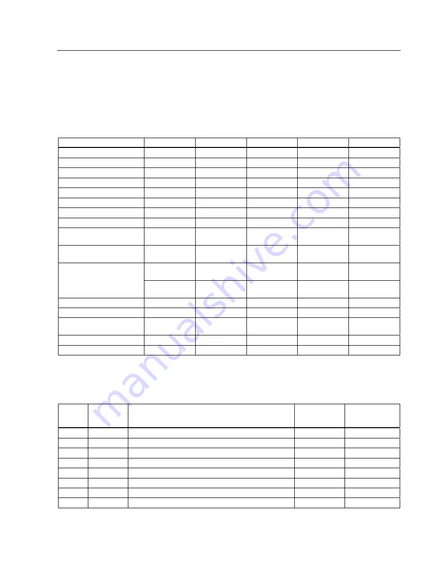
Table 3-1
Interfaces of the Control Units CU240S
Control Unit
CU240S
CU240S DP
CU240S DP-F
CU240S PN
CU240S PN-F
Digital Inputs
9
9
6
9
6
Fail-safe digital Inputs
--
--
2
--
2
Digital Outputs
3
3
3
3
3
Analog Inputs
2
2
2
2
2
Analog Outputs
2
2
2
2
2
PTC/KTY84 interface
x
x
x
x
x
Encoder interface
1, TTL or HTL
1, TTL or HTL
1, TTL or HTL
1, TTL or HTL
1, TTL or HTL
Ext. 24 V
x
x
x
x
x
MMC interface /
MMC slot
x
x
x
x
x
Option port
Starter or
BOP interface
Starter or
BOP interface
Starter or
BOP interface
Starter or
BOP interface
Starter or
BOP interface
USS on RS485
PROFIBUS
PROFIBUS,
PROFIsafe
PROFINET
PROFINET
Bus interface
SUB-D
connector
SUB-D
connector
SUB-D
connector
RJ45
RJ45
PROFIBUS DP DIP switches
--
x
x
--
--
General I/O DIP switches
x
x
x
x
x
Power module interface (PM-
IF)
x
x
x
x
x
Terminals
x
x
x
x
x
Status LEDs
2
3
7
7
11
Terminals
Table 3-2
Control terminals
Terminal Designation Function
CU240S;
CU240S DP;
CU240S PN
CU240S DP-F
CU240S PN-F
1
+10V OUT
Non-isolated 10 V, max. 10 mA
x
x
2
0V OUT
Supply reference (terminal 1)
x
x
3
AI0+
Analog input 0 positive
x
x
4
AI0-
Analog input 0 negative
x
x
5
DI0
Digital input 0, isolated
x
x
6
DI1
Digital input 1, isolated
x
x
7
DI2
Digital input 2, isolated
x
x
8
DI3
Digital input 3, isolated
x
x


