


Chapter
6
Operating Instructions
Flexi Soft Gateways
136
© SICK AG • Industrial Safety Systems • Germany • All rights reserved
8012664/XB29/2013-06-11
Subject to change without notice
Fieldbus gateways
6.2.3
CANopen configuration of the gateway — Which data are transferred
Each CANopen device stores its data in
objects
that are listed in the
object dictionary
.
Ser-
vice data objects
(SDOs) mainly contain the CANopen configuration data, while the process
data are stored in
process data objects
(PDOs).
Communication objects
are used to read
and write these SDOs and PDOs as well as to control the devices. A detailed description of
the different objects will be given in the following sections.
Predefined connection set (PCS)
The predefined connection set provides a simple CAN identifier structure. The FX0-GCAN
gateway provides
communication objects
that can be addressed or sent using these CAN
identifiers.
The PCS comprises 2 broadcast objects (NMT and SYNC) and a total of 12 peer-to-peer ob-
jects. Each of these objects has a unique 11 bit CAN identifier that consists of a function
code and a device address. The device address for the broadcast objects is 0, for the other
objects 1 … 127.
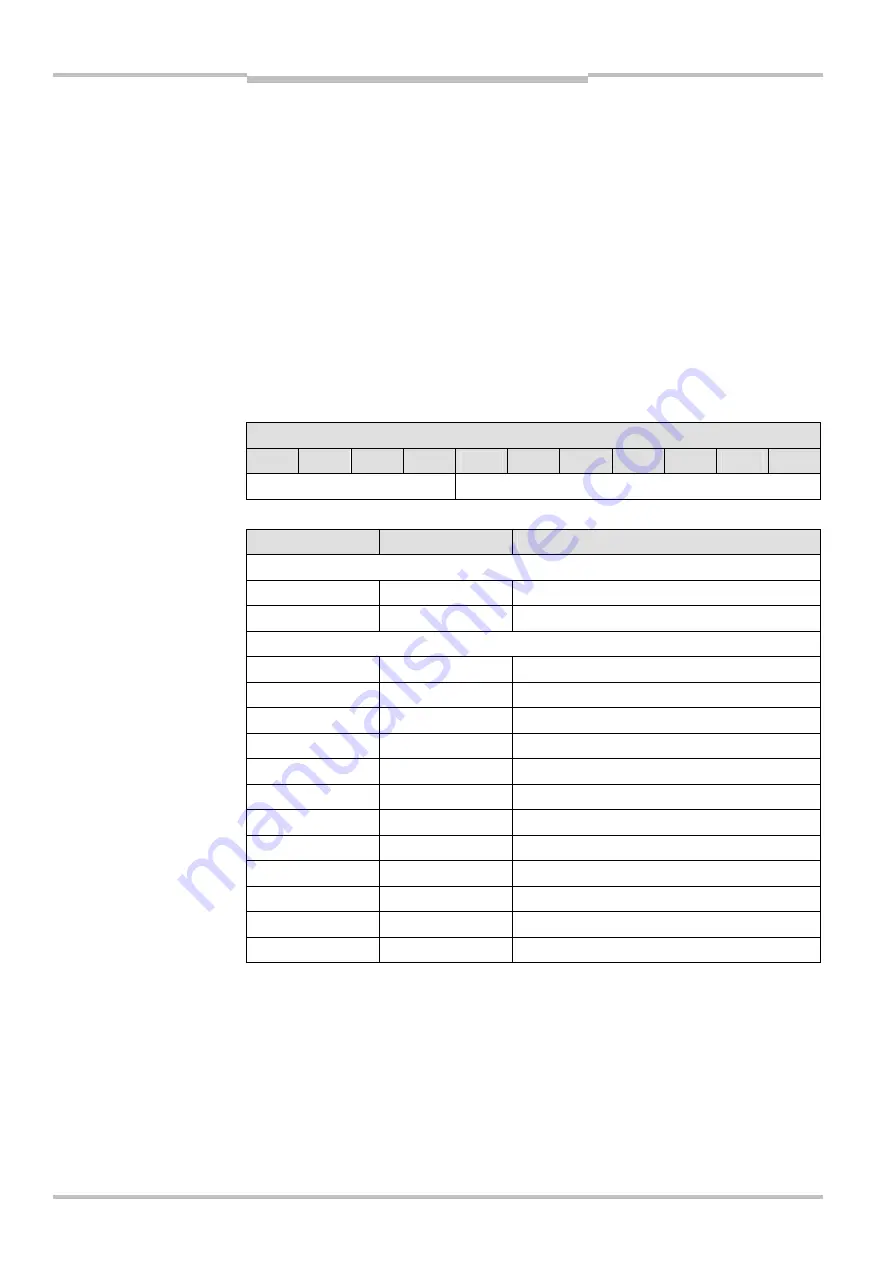
Bit number
10
9
8
7
6
5
4
3
2
1
0
Function code
Device address
Object
CAN identifier
Meaning
Broadcast objects
NMT 00h Network
management
SYNC 80h Sync
message
Peer-to-peer objects
EMERGENCY
081h … 0FFh
Status message
TxPDO1
181h … 1FFh
Send process data object 1
RxPDO1
201h … 27Fh
Receive process data object 1
TxPDO2
281h … 2FFh
Send process data object 2
RxPDO2
301h … 37Fh
Receive process data object 2
TxPDO3
381h … 3FFh
Send process data object 3
RxPDO3
401h … 47Fh
Receive process data object 3
TxPDO4
481h … 4FFh
Send process data object 4
RxPDO4
501h … 57Fh
Receive process data object 4
TxSDO
581h … 5FFh
Send service data object
RxSDO
601h … 67Fh
Receive service data object
NMT-ErrorControl
701h … 77Fh
Node guarding
Each object starts with its CAN identifier, followed by the RTR bit (Remote Transmission
Request), followed by the Data Length Code (DLC), followed by 0 to 8 data bytes. The DLC
(4 bits) indicates the number of data bytes.
Tab. 98: CAN identifier
structure
Tab. 99: PCS communication
objects