background image

4-9

4

P

rin
t mode and special prin

ting

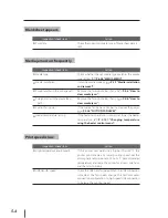
Double-sided printing

16

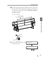
Start printing on the 2nd side of the media.

Note

Note that the data transfer from the RIP differs by 180 degrees between first side 
and 2nd side.

Summary of Contents for IP-7900

Page 1: ...r s Guide Solvent Ink Color Inkjet Printer IP 7900 Read this User s Guide carefully before use of this printer and handle it properly After reading keep it for later use U00112722602 Seiko I Infotech...

Page 2: ...92029 USA Tel 1 760 781 5200 Fax 1 760 745 1195 Seiko I Infotech Inc 8 Nakase 1 chome Mihama ku Chiba shi Chiba 261 8507 Japan Phone 81 43 211 1363 Fax 81 43 211 8709 This guide acknowledges the follo...

Page 3: ...he EMC directive 2004 108 EC and low voltage directive 2006 95 EC Inquiry of CE mark Seiko Instruments Europe S A European Head Office Avenue de Messidor 198 1180 Brussels Belgium Phone 32 0 2 346 62...

Page 4: ...kjet Printer User s Guide describes such information for use as features and names of parts of the printer and basic operations including power ON OFF and media ink setting The following items should...

Page 5: ...ot Basic configuration item Printer 1 unit equipped with USB interface mounted with the roll feed unit and take up reel unit Items packed with printer Components delivered with this product Scroller 2...

Page 6: ...quid 200 ml Spittoon absorber liquid 100 ml Cleaning roller 30 pieces Cleaning swab 10 pieces Dripper 10 pieces Tweezers 1 piece Cleaning stick 1 piece Spittoon case 1 piece Gloves 30 pairs Bag 1 piec...

Page 7: ...kit IP7 130 1 set Cap cleaning liquid 300 ml Wiper cleaning liquid 200 ml Spittoon absorber liquid 100 ml Cleaning roller 30 pieces Cleaning swab 10 pieces Dripper 10 pieces Tweezers 1 piece Cleaning...

Page 8: ...ink bottle IP6 609 1 bottle Head cleaning kit IP7 125 Consumables can be ordered separately Cleaning roller set IP5 121 90 pieces Wiper blade IP7 133 8 pieces Absorbent sheet IP7 124 1 roll Spittoon...

Page 9: ...ertain procedure or operation This symbol denotes items that are forbidden This symbol denotes items you should follow to prevent accidents or injury Minor personal injury or product and or peripheral...

Page 10: ...ouch the internal parts of the printer Doing so may cause fire electric shock or a breakdown DO NOT disconnect or connect the power cable with wet hands Doing so may lead to electric shock Turn the pr...

Page 11: ...r foot you may be injured Always hold the power cable or USB cable by the plug or the connector when connecting or disconnecting the power cable or USB cable Never pull the cable directly because this...

Page 12: ...nter off 5 Do not clean the surface of the cover with benzene or paint thinner The coating may come off or deteriorate Clean the cover with a soft cloth If the cover is very dirty wipe it off with a c...

Page 13: ...perature and direct sunlight Doing so may deteriorate ink characteristic 8 Do not disassemble ink pack Printer warranty 1 To understand the printer s performances and functions well and use the printe...

Page 14: ...ION Boxes marked with a CAUTION describe points of caution for avoiding injury to yourself or damage to the printer Note They explain the important items and cautions that should be kept for operation...

Page 15: ...n menu It shows the key on the operation panel It shows the LCD on the operation panel ON lighting Blink OFF lights out Example 2 LED marks in a sentence It shows the key used for selection Example Se...

Page 16: ...ence INITIALIZING PLEASE WAIT It shows the key on the operation panel INK MEDIA REG MEDIA M ADV REWIND FORM FEED PH REC PH MAIN It shows that the LCD menu automatically changes in the arrow direction...

Page 17: ...liquid kit 1 10 Head cleaning kit 1 10 Spittoon absorber liquid 1 11 Subcartridge 1 11 Wiper blade 1 11 Cleaning stick 1 11 Cleaning roller set 1 11 Spittoon case set 1 12 Ink tray 1 12 Glove set 1 12...

Page 18: ...____________2 49 Ink pack installation replacement procedure 2 49 Replacing ink pack when ink is exhausted 2 52 When no ink pack is installed 2 55 Service clean 2 55 Head wash 2 61 8 color to 4 color...

Page 19: ...operation panel LCD display and state of the printer ______________________________________3 2 How to read LCD display 3 2 Online operation ______________________________________________________3 6 Ba...

Page 20: ...____________________________5 15 How to get good image quality _________________________________________5 16 The print is light 5 16 White stripes appear on the print 5 16 Black stripes appear on the...

Page 21: ...ion basic knowledge needed before using the printer After reading this section proceed to section 2 Content of this section Operating conditions 1 2 Consumables 1 4 Appearance Name and function of eac...

Page 22: ...inter for supplies replacement of consumables and parts print processing and ventilation during normal operation and maintenance Keep the space shown in the figure below Installation and maintenance s...

Page 23: ...r the print quality may be degraded It takes time for the printer to reach the operating environment temperature and humidity To get good print image quality it is recommended to keep the room tempera...

Page 24: ...pening the package Put media in the packing box to prevent dust and store media in a cool and dark place Avoid rapid change of temperature and humidity and store media with no condensation Do not stor...

Page 25: ...Correct distortion of roll media before loading Precautions for handling prints Do not touch the print surface before the ink dries within 24 hours after printing in particular Handle by edges of the...

Page 26: ...1500 ml IP7 107 Gy gray 1500 ml IP7 108 Lgy light gray 1500 ml Note Always use these specified ink packs Failure to use the recommended ink pack may lead to a deterioration of the print quality or a p...

Page 27: ...UTION Do not swallow ink or avoid its splashes on the eye to prevent breathing trouble or visual impairment If ink gets into the eye wash it off with clean running water and consult a doctor If it is...

Page 28: ...orcefully but consult a doctor Note Install the waste ink bottle securely A waste ink bottle must always be installed When it is removed for disposal of waste ink another empty waste ink bottle must b...

Page 29: ...eezers 1 piece Spittoon case 1 piece Gloves 30 pieces Bag 1 CAUTION Do not swallow cleaning liquid or avoid its splashes on the eye to prevent breathing trouble or visual impairment If cleaning liquid...

Page 30: ...Bag 6 pieces Storage liquid kit Type Content Quantity IP7 137 Storage liquid pack 8 pieces Dummy subcartridge 8 pieces Cleaning liquid kit Type Content Quantity IP7 136 Cleaning liquid pack 8 pieces D...

Page 31: ...nta 400 ml IP7 113 C cyan 400 ml IP7 114 K black 400 ml IP7 115 Lc light cyan 400 ml IP7 116 Lm light magenta 400 ml IP7 117 Gy gray 400 ml IP7 118 Lgy light gray 400 ml Wiper blade Type Content Quant...

Page 32: ...y Type Content Quantity IP7 123 Ink tray 1 piece Glove set Type Content Quantity IP7 138 Gloves 100 pairs Absorbent sponge Option for mesh banner Type Content Quantity IP7 127 Absorbent sponge 10 piec...

Page 33: ...dia press force P 2 105 Front cover Must be closed during printing Waste ink bottle unit A unit to contain a waste ink bottle P 2 87 Cap cover Opened when cleaning the capping unit or replacing the wi...

Page 34: ...ater power inlet Heater power switch USB connector Connected to the printer server P 2 2 Subcartridge An auxiliary ink for printing even during replacement of ink Take up reel switch P 2 14 Media feed...

Page 35: ...eheater rear Preheats media Print heater front Penetrates ink into media to fuse the ink Afterheater finishing Dries ink to stabilize print quality These three heaters are controlled independently The...

Page 36: ...panel is also equipped with a buzzer function for attention in case an error occurs or an invalid input is entered OK MENU ONLINE HEATER CANCEL LCD Indicates printer status and menus B Power switch A...

Page 37: ...cut sheet media is loaded E ONLINE LED Green Indicates online or offline state of the printer ON Online Blink Online pause mode OFF Offline Key ONLINE key Used to select online or offline of the print...

Page 38: ...15 An optional scroller available for both the roll feed unit and take up reel unit Exhaust attachment IP7 013 An optional unit to attach an exhaust duct to the printer PS RIP PhotoPrint 6 Standard SI...

Page 39: ...bottle installation and replacement 2 87 Replacing the wiper blade 2 90 Correcting the edge sensor position 2 92 Adjusting tension bar length 2 94 Print head cleaning 2 95 Feeding the media Feed 2 97...

Page 40: ...the printer Note Use the supplied USB2 0 cable USB connector USB2 0 cable B type connector When using a USB hub use a product that supports USB2 0 Use USB IF certified products for cables and hub use...

Page 41: ...r lines Note that both of them are 200 VAC Printer power switch Printer power inlet Heater power switch Heater power inlet Turn on the Printer power switch and Heater power switch first and then use t...

Page 42: ...Switch off O Power inlet Power outlet 200 VAC 15A in Japan 2 Turn on I the Printer and Heater power switches on the rear panel Switch on I Note Do not use any power cable other than those supplied wi...

Page 43: ...ssage PRINTER READY is displayed If the power is turned off unnecessarily when the printer is performing INITIALIZING or CLEANING the ink may drip or the print head may be damaged or saved parameters...

Page 44: ...UTTING DOWN PLEASE WAIT The message is displayed on the LCD as shown above indicating that the shutdown process is in progress The power is turned off after the shutdown process is completed To keep t...

Page 45: ...sheet feed Roll media installation procedure 1 Put the media on the table If you want to use a dolly contact us We have a recommend product 2 Adjust the roll spacer position according to the media wid...

Page 46: ...p Inner take up 2 Determine the distance between the media edge and the flange with the paper setting gauge 3 Rotate the handle clockwise as far as it will go and then secure the scroller at the point...

Page 47: ...by fitting it with the roll groove of the printer Printer rear supply side Roll groove Scroller To set the scroller alone Use a recommended dolly Scroller Recommended dolly To set the scroller manuall...

Page 48: ...over Front cover Protection bar 7 Move the media edge guards to each side so that they are not under the media Media edge guards 8 Rotate the pressure control knob clockwise to raise the pressure roll...

Page 49: ...is hard to insert the media end into the paper feeder due to a curl of the media interpose an interleaf and insert the media end under the interleaf as shown in the left figure 10 Feed the media until...

Page 50: ...perly 12 Rotate the pressure control knob counterclockwise to lower the pressure roller Takeup side Supply side or Pressure control knobs 13 Set the media edge guards and close the front cover CHECK E...

Page 51: ...yed at the end of the registered media Press the key to enter MEDIA REG MENU The media registration procedure is the same as the registration from the registration menu P 3 30 MEDIA REG MENU Press the...

Page 52: ...part Then create a slack between the platen and the peel roller by carrying the tension bar to the rear side of the peel roller with a supply side feed switch black Switch Tension bar Tension bar Adj...

Page 53: ...lack Slacken off to a level lower than the supply side slack sensor When the slack reaches the sensor detection area the operation panel blips Supply side slack sensor Peel roller Scroller Note Be sur...

Page 54: ...nts the paper tube from bending at the center due to the media weight Roll spacer Scroller Do not move this roll spacer 1 Remove the two screws and move the roll spacer to the center of the media Ther...

Page 55: ...eeth Push it as far as it will go 2 Match the flange stopper with the claw of the flange spacer and then tighten the knob to secure the flange spacer and the flange stopper 4 Set the take up direction...

Page 56: ...e of the printer Scroller Roll groove Note Hook the tension bar to the tension bar hook beforehand Tension bar hook Tension bar 6 Feed the media with the FORM FEED MENU on the operation panel to an ex...

Page 57: ...and then make sure that the media is not deviated on the supply side and the takeup side 2 With tape hold the media straight at the center and then at the rest six positions in the direction from the...

Page 58: ...If the tension bar is attached without winding the media by one turn the tape will peel off 10 Advance the media with the FORM FEED MENU on the operation panel to an extent where a slack can be create...

Page 59: ...t tension bar was placed securely at the tension bar guide s bottom 13 Close the tension bar guide s cover 14 Press the take up direction switch according to the take up direction Take up direction sw...

Page 60: ...ange to wind the media such as PCV which may cause winding deviation frequently Set the paper tube flange directly to the scroller without spacers when the TUR side paper tube is longer than supply si...

Page 61: ...spacer of the figure and move the roll spacer to the center of the media Note that three positions are available to relocate the removed roll spacer Select one position depending on the media width 2...

Page 62: ...er Rubber Spacer A 5 Fix the flange spacer and the flange stopper on the paper tube Flange spacer Rubber Spacer A Flange stopper Push the flange spacer all the way in the paper tube Notches at four po...

Page 63: ...roll the media until the media can be wound with the operation panel s FEED menu 9 Adjust the paper tube position Media Clear this gap Knob Flange Paper tube Confirm that no gap is found between the l...

Page 64: ...ing at all 3 to 5mm gap to be secured at the both media edges Paper tube flange fixing screws at three positions NOTE1 Rotate the take up roll with the procedure below a Cover the sensor window by sli...

Page 65: ...ber Spacer A Rubber Spacer B 11 Attach the media to the paper tube Confirm that the media is wound in outer side take up mode With adhesive tape hold the media straight at the center and then at the r...

Page 66: ...lign the right end of the cut sheet with the guideline and insert the cut sheet into the paper feeder 4 Rotate the pressure control knob counterclockwise to lower the pressure roller 5 Set the media e...

Page 67: ...The media registration procedure is the same as the registration from the registration menu P 3 30 MEDIA REG MENU Press the key to return from the media registration menu to the media type selection m...

Page 68: ...witch Take up direction switch OFF Outer take up OFF Inner take up 2 Open the tension bar guide s cover 3 Place the tension bar at the tension bar hook Detach the tension bar at the take up sides In c...

Page 69: ...to the guides Do not remove these nets When cutting the media be careful not to damage the paper guide net Pay attention not to drop the used media so as to avoid messing up the floor 5 Set the printe...

Page 70: ...yer fan Note When the media dryer fan is turned upward it slightly goes down and is fixed To return the fan to its original position pull it up and turn it toward you and then push it and secure it wi...

Page 71: ...n Media installation and removal 12 Loosen the knob screw of each tension bar hook and extend it laterally Knob screw Tension bar hook 13 Set a dolly under the media and lift the media to remove it Re...

Page 72: ...key The TUR s take up switch is activated by selecting media 3 Lift the slackened part and remove the tension bar at the supply side Peel roller Scroller Media in general Tension bar Vinyl chloride me...

Page 73: ...eration Media installation and removal 4 Rotate the pressure control knob clockwise to raise the pressure roller Takeup side Supply side or Pressure control knobs 5 Rotate the scroller manually to tak...

Page 74: ...printer Printer rear supply side Scroller Roll groove To set the scroller alone Use a recommended dolly Scroller Recommended dolly To set the scroller manually by two persons Use the supplied scrolle...

Page 75: ...counterclockwise 2 When a gap is generated between the handle and the scroller shaft remove the scroller Note Do not touch the claw of the scroller When no media is loaded on the scroller 1 The messag...

Page 76: ...ength for one time print To cancel printing of media advance correction pattern press the CANCEL key 2 Set the printer to the offline mode Press the O N L I N E key INK MEDIA REG MEDIA M ADV 3 Press t...

Page 77: ...rom them 7 Press the key and then the key to display the media advance correction value MEDIA ADV VALUE 01 099 80 8 Enter the media advance correction value and press the key Align the digit with the...

Page 78: ...o return to the offline state For changing media advance correction value during printing refer to P 3 8 In case of small media advance correction value In case of appropriate media advance correction...

Page 79: ...of ADJUST PH POS STEP1 Print the test pattern for ADJUST PH POS 1 Set the printer to the offline state Press the O N L I N E key INK MEDIA REG MEDIA M ADV 2 Press the M E N U key twice to display the...

Page 80: ...ection value 7 Select the menu group that includes ADJUST and press the key to display PH TO PH VAL PH TO PH VAL Y 00 8 Move the cursor with the key and select the print head color with the and keys P...

Page 81: ...ight test patterns for Lc print head the two lines misalign at 21 while they overlap at 2 So input 2 for the correction value 2 21 Lc Lc PH TO PH VAL Lc 02 11 Press the key PH TO PH VAL Lc 02 12 Input...

Page 82: ...the key to select ADJUST PH R L and press the key NOZZLE PRINTS ADJUST PH R L 5 Confirm that the NOZZLE PRINTS are ready NOZZLE PRINTS OK 6 By pressing the key print the test pattern below NOZZLE PRI...

Page 83: ...n the ADJUST PH R L patterns select a pattern where the print head s two lines overlap to be one line Then input the selected pattern s value Then input the selected pattern s value press the and keys...

Page 84: ...the printer is not warmed up sufficiently For the procedure to warm up the media heater forcedly see P 2 102 STEP1 Printing the test pattern for BIDIRECTION 1 Set the printer to the offline state Pres...

Page 85: ...ADJUST and press the key to display BIDIR ADJ BIDIR ADJ XXXXXX Y 00 Note the indicates the numbers 1 to 4 and that indicates R or L 8 Move the cursor with the key and select the print head color with...

Page 86: ...d keys to input the value 8 21 M M Input the value of the test pattern where each print head s two lines overlap with the least misalignment For example on the right test patterns for M print head the...

Page 87: ...ure When the ink pack is not recognized When the ink charge from ink tray is not completed Note Do not remove ink tray in the following cases Otherwise ink may spill in the printer depending on the pr...

Page 88: ...rinter Ink tray 3 Take the empty ink pack out of the ink tray If ink is not installed go to step 4 Push the two claws at the lower part of the plate of the ink pack and pull up the plate Then remove t...

Page 89: ...e ink pack on the ink tray s two protrusion Then insert the plate into the ink tray until a click is heard 2 1 New ink pack Plate Protrusion Ink tray 5 Insert the ink tray into the slot of the printer...

Page 90: ...k is remaining in the subcartridge even during replacement of ink print operation is performed Replacing ink pack when ink is exhausted 1 The error message is displayed OPEN INK COVER XXX REPLACE INK...

Page 91: ...ened PRINTING ROLL 104 PAPER PRINTING CLOSE PRINTING COVER The guidance message to prompt you to close the ink box cover appears in the second line of the LCD While ink is remaining in the subcartridg...

Page 92: ...without interruption If the ink pack has not been replaced before the ink in the subcartridge is exhausted the printer enters the print pause mode and print operation is interrupted until the ink pac...

Page 93: ...Magenta Gy4 Gray Lg8 Light gray 4 color mode Y1 Yellow K5 Black M2 Magenta C6 Cyan C3 Cyan M7 Magenta K4 Black Y8 Yellow 2 Install the specified ink pack according to Ink pack installation replacement...

Page 94: ...ges LOAD XXX DUMMY SUBCART XXX Ink color and position 8 color mode Y1 Yellow K5 Black Lm2 Light magenta Lc6 Light cyan C3 Cyan M7 Magenta Gy4 Gray Lg8 Light gray 4 color mode Y1 Yellow K5 Black M2 Mag...

Page 95: ...NK COVER 7 Remove the eight ink trays Ink trays to be removed REMOVE XXX INK PACK XXX Ink color and position 8 color mode Y1 Yellow K5 Black Lm2 Light magenta Lc6 Light cyan C3 Cyan M7 Magenta Gy4 Gra...

Page 96: ...OPEN INK COVER 11 Insert the ink trays with storage liquid packs into the slot of the ink box Ink trays to be set LOAD XXX SL PACK For how to install ink packs refer to Ink pack installation replaceme...

Page 97: ...panel to perform cleaning START SL CHARGING BOTTLE OK CHARGING SL PLEASE WAIT XXX 14 Open the ink box cover Knob Ink box cover OPEN INK COVER 15 Remove the ink trays with cleaning liquid packs Ink tr...

Page 98: ...PURGING BOTTLE OK PURGING PLEASE WAIT XXX 18 Open the ink box cover Knob Ink box cover OPEN INK COVER 19 Insert the ink trays with storage liquid packs into the slot of the ink box Ink trays to be set...

Page 99: ...CHARGING SL PLEASE WAIT XXX Head wash 1 Execute the CLEAN INK SYS from the operation panel INK SYSTEM OPT CLEAN INK SYS 2 Loosen the two knob screws on the subcartridge cover and open the subcartridg...

Page 100: ...Dummy subcartridges LOAD XXX DUMMY SUBCART 5 Close the subcartridge cover and tighten the two knob screws Subcartridge cover CLOSE SUBCARTRIDGE COVER 6 Open the ink box cover Knob Ink box cover OPEN...

Page 101: ...Lm2 Light magenta Lc6 Light cyan C3 Cyan M7 Magenta Gy4 Gray Lg8 Light gray 4 color mode Y1 Yellow K5 Black M2 Magenta C6 Cyan C3 Cyan M7 Magenta K4 Black Y8 Yellow 8 Close the ink box cover Ink box...

Page 102: ...pack installation replacement procedure To facilitate this work set the cleaning liquid packs to the optional ink trays in advance 12 Close the ink box cover Ink box cover CLOSE INK COVER 13 Press the...

Page 103: ...Y1 Yellow K5 Black Lm2 Light magenta Lc6 Light cyan C3 Cyan M7 Magenta Gy4 Gray Lg8 Light gray 16 Close the ink box cover Ink box cover CLOSE INK COVER 17 Press the key on the operation panel to perf...

Page 104: ...cleaning liquid packs Ink trays to be removed REMOVE XXX CL PACK 21 Close the ink box cover Ink box cover CLOSE INK COVER 22 Press the key on the operation panel to perform ink removal START PURGING...

Page 105: ...s described below Note If 8 color data is received during the 4 color mode an error is notified at the host computer side Print operation is disabled To change the color mode to the 4 color mode purch...

Page 106: ...Ink color and position Y1 Yellow K5 Black Lm2 Light magenta Lc6 Light cyan C3 Cyan M7 Magenta Gy4 Gray Lg8 Light gray 4 Set the dummy subcartridges of the color replacement set Dummy subcartridges LOA...

Page 107: ...eaning twice 6 Open the ink box cover Knob Ink box cover OPEN INK COVER On the LCD ink box cover is indicated as INK COVER 7 Remove the ink trays Lm Lc Gy and Lgy for the 8 color mode Ink trays to be...

Page 108: ...cleaning liquid packs into the slots of the ink box Ink trays to be set Ink trays to be set LOAD XXX CL PACK XXX Ink color and position Y1 Yellow K5 Black Lm2 Light magenta Lc6 Light cyan C3 Cyan M7 M...

Page 109: ...E INK COVER 13 Press the key on the operation panel to perform cleaning START CL CHARGING BOTTLE OK CHARGING INK PLEASE WAIT XXX 14 Open the ink box cover Knob Ink box cover OPEN INK COVER 15 Remove t...

Page 110: ...17 Press the key on the operation panel to perform ink removal START PURGING BOTTLE OK PURGING PLEASE WAIT XXX 18 Repeat the steps10 to17 to perform the cleaning again 3 Set the 4 color mode s ink pac...

Page 111: ...XX INK PACK For procedure to install ink packs refer to Ink pack installation replacement procedure To facilitate this work set the ink packs to the optional ink trays in advance 21 Close the ink box...

Page 112: ...ridge cover and open the subcartridge cover Subcartridge cover Knob screws OPEN SUBCARTRIDGE COVER 24 Remove the dummy subcartridges of the color replacement set Subcartridges to be removed REMOVE XXX...

Page 113: ...s classified into four actions as follow 1 Replace the four subcartridges with four dummy subcartridges 2 Remove the four ink trays and perform the cleaning twice 3 Set the 8 color mode s ink packs 4...

Page 114: ...Remove the two knob screws on the subcartridge cover and open the subcartridge cover Subcartridge cover Knob screws OPEN SUBCARTRIDGE COVER 3 Remove the subcartridges Y M C and K for the 4 color mode...

Page 115: ...ubcartridges of the color replacement set Dummy subcartridges LOAD XXX DUMMY SUBCART 5 Close the subcartridge cover Subcartridge cover CLOSE SUBCARTRIDGE COVER 2 Remove the four ink trays and perform...

Page 116: ...XXX Ink color and position Y1 Yellow K5 Black M2 Magenta C6 Cyan C3 Cyan M7 Magenta K4 Black Y8 Yellow 8 Close the ink box cover Ink box cover CLOSE INK COVER 9 Press the key on the operation panel to...

Page 117: ...rays to be set LOAD XXX CL PACK For how to install ink packs refer to Ink pack installation replacement procedure To facilitate this work set the ink packs to the optional ink trays in advance 12 Clos...

Page 118: ...EMOVE XXX CL PACK XXX Ink color and position Y1 Yellow K5 Black Lm2 Light magenta Lc6 Light cyan C3 Cyan M7 Magenta Gy4 Gray Lg8 Light gray 16 Close the ink box cover Ink box cover CLOSE INK COVER 17...

Page 119: ...COVER 20 Set the ink trays Lm Lc Gy and Lgy for the 8 color mode Ink trays to be set Ink trays to be set LOAD XXX INK PACK For the procedure to install ink packs refer to Ink pack installation replace...

Page 120: ...two knob screws on the subcartridge cover and open the subcartridge cover Subcartridge cover Knob screws OPEN SUBCARTRIDGE COVER 4 Replace the four dummy subcartridges with the four subcartridges 24...

Page 121: ...color mode Subcartridges LOAD XXX DUMMY SUBCART 26 Close the subcartridge cover and tighten the two knob screws Subcartridge cover CLOSE SUBCARTRIDGE COVER 27 Press the key on the operation panel STA...

Page 122: ...n Error code 2 Reinstall the ink pack according to Ink pack installation replacement procedure Note Unrecognized ink pack cannot be used If the guidance message is still displayed after the ink pack i...

Page 123: ...s to be removed Ink trays to be removed REMOVE XXX DUMMY INK PACK XXX Ink color and position 8 color mode Y1 Yellow K5 Black Lm2 Light magenta Lc6 Light cyan C3 Cyan M7 Magenta Gy4 Gray Lg8 Light gray...

Page 124: ...2 86 7 Close the ink box cover Ink box cover CLOSE INK COVER 8 Press the key INK SUPPLY OK INK SUPPLY EXECUTING INK SUPPLY...

Page 125: ...waste ink bottle becomes full 3 Confirm the message to select the waste ink counter reset clear is displayed BOTTLE EMPTY NO BOTTLE EMPTY YES Note The waste ink counter counts the amount of waste ink...

Page 126: ...2 The ink drips from the tube Leave it for a while 3 Remove the full waste ink bottle from the unit paying attention not to spill the waste ink Then cap it and replace it with a new one 4 Wipe off th...

Page 127: ...Procedure when no waste ink bottle is installed 1 Confirm that the printer recognizes no waste ink bottle with the guidance message is displayed BOTTLE OUT INSTALL BOTTLE 2 Install a new waste ink bot...

Page 128: ...ey to display PH MAIN MENU REWIND FORM FEED PH REC PH MAIN 2 Press the key to enter PH MAIN MENU The cap cleaning menu is displayed CAP CLEANING 3 Select REPLACE WIPER BLADE with the key and press the...

Page 129: ...and front cover REPLACE FINISHED NO 10 Select YES and press the key to finish the replacement REPLACE FINISHED YES Note The printer automatically adds up the usage time period of the wiper blade and...

Page 130: ...il the CHECK EDGE SENSOR menu appears TEST PRINTS CHECK EDGE SENSOR 5 Press the key TEST PRINTS OK 6 Press the key TEST PRINTS EXECUTING 7 Judge the printing results Measure the margin of the printing...

Page 131: ...rn enter the correction value of the edge sensor position EDGE SENSOR ADJ VAL Y Ymm 11 Press the key to decide the entered value EDGE SENSOR ADJ VAL 0 0mm 12 Press the key to return to the higher leve...

Page 132: ...Coupling tension bars supply side Tension bars can be connected to each other by screwing The length of these four tension bars is 104 inches when connected The L size tension bar whose both ends are...

Page 133: ...DIA REG MEDIA M ADV 2 Press the M E N U key to display PH REC MENU INK MEDIA REG MEDIA M ADV M E N U REWIND FORM FEED PH REC PH MAIN 3 Press the key to enter the head cleaning menu PH RECOVERY NORMAL...

Page 134: ...Selected head numbers 9 Check visually that the waste ink bottle is not full and press the key once again PH RECOVERY CLEANING XXX XXX This value is counted down every 10 seconds Note Print head clean...

Page 135: ...s FORM FEED MENU REWIND FORM FEED PH REC PH MAIN 3 Keep pressing the key While the key is pressed the media is fed FEEDING MEDIA 4 When the key is released the printer stops feeding the media and retu...

Page 136: ...d the printer stops backfeeding the media and returns to the offline state menu mode REWIND FORM FEED PH REC PH MAIN When the key is pressed in the online state idle mode the printer can backfeed medi...

Page 137: ...ration as immediately as possible Or perform the cleaning as the print heads dry and the print image quality is affected Nest function 1 Return the media by operating Back Feed P 2 98 Backfeeding the...

Page 138: ...rriage returns and the printer enters the online state idle mode and becomes ready to print NEST ORIGIN SETTING OK NEST ORIGIN SETTING PLEASE WAIT PRINTER READY NEST 1625 PAPER To cancel the set origi...

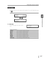
Page 139: ...or to monitor the current heater temperature Heater control menu display Press the HEATER key to display the heater control menu Centigrade temperature display A f t 40 P r n 45 P r e 45 C 40 C 40 C...

Page 140: ...trol stops To finish displaying the heater control menu Press the HEATER key while the heater control menu is displayed Even if heater temperature is changed in the heater control menu the initial tem...

Page 141: ...set to a high temperature the printer lowers the printing speed automatically in some cases to maintain stable print quality Set the afterheater and preheater temperatures so that they are nearly 5 C...

Page 142: ...is completed the set temperature changed in the heater control menu remains as set temperature However the initial temperature value of each heater stored in MEDIA REG MENU remains unchanged 5 The su...

Page 143: ...used when installing media It can be turned both clockwise and counterclockwise The pressure control knob is provided on the supply side and takeup side The pressure force can be adjusted on the suppl...

Page 144: ...hand excessive head height from the media will also degrade the print quality Use the printer with the head height that is automatically adjusted by the printer 1 Set the printer to the offline state...

Page 145: ...area Reduces the effect of the suction fan Note Make the media edge guard usage setting in the MEDIA REG MENU from the operation panel The right and left margins of the media are controlled by this s...

Page 146: ...edge guard 2 117 Performing normal cleaning 2 117 Performing nozzle print 2 117 2 Bimonthly inspection and maintenance Cleaning the print head 2 118 Replacement of the spittoon case 2 118 3 Maintenanc...

Page 147: ...ry out these items everyday Be sure to use the cleaning liquid and cleaning swabs specified by us Checking the wiper blade for contamination Visually check the wiper blade for contamination and scratc...

Page 148: ...e wiper cleaning liquid level through the cleaning liquid port at the lower right of the top face of the wipe unit If the liquid lever is below the top of the mark that can be seen inside the cleaning...

Page 149: ...AIN MENU INK MEDIA REG MEDIA M ADV 3 Press the key to enter PH MAIN MENU The cap cleaning menu is displayed CAP CLEANING 4 Press the key When the confirmation screen appears press the key again The ca...

Page 150: ...is intended for a single use only Use a new cleaning roller for each cleaning 8 Close the cap cover and the front cover The print head returns automatically to the home position Note Do not leave the...

Page 151: ...id quantity measurement is visible refill the spittoon absorber liquid up to the same level as the top of the boss If the spittoon absorber liquid should be replaced P 2 118 Replacement of the spittoo...

Page 152: ...rinter to the offline state and press the M E N U key to display PH MAIN MENU REWIND FORM FEED PH REC PH MAIN 2 Press the key to enter PH MAIN MENU The cap cleaning menu is displayed CAP CLEANING 3 Pr...

Page 153: ...ning stick in the cap cleaning liquid Note Do not soak the cleaning stick that you used for cleaning in the cap cleaning liquid bottle The cap cleaning liquid will be contaminated 7 Move the carriage...

Page 154: ...ng stick Carriage Head guard gray parts 9 Move the carriage manually onto the platen left side and secure the spittoon unit with the knob screw Knob screw Spittoon unit 10 Close the cap cover and then...

Page 155: ...AL ALL for cleaning Performing nozzle print Select ADJUST MENU from the operation panel and select TEST PRINTS to perform the nozzle print Check for nozzle out and incorrect print The nozzle print is...

Page 156: ...Exchange the spittoon absorber liquid at the same time 1 Set the printer to the offline state and press the M E N U key to display PH MAIN MENU REWIND FORM FEED PH REC PH MAIN 2 Press the key to enter...

Page 157: ...case to discharge the spittoon absorber liquid to the backside The discharged spittoon absorber liquid will go into the waste ink bottle When discharge is completed put the spittoon absorber liquid ca...

Page 158: ...orbed by the sponge which may lower the liquid s top surface In such a case apply the liquid additionally Spittoon unit Liquid level Top of the boss 10 Close the cap cover and then close the front cov...

Page 159: ...liquid kit P 1 10 The storage liquid kit contains eight storage liquid packs and eight dummy subcartridges Use the eight storage liquid packs completely in a single service clean Service clean P 2 55...

Page 160: ...d then select the head wash INK SYSTEM OPT CLEAN INK SYS After the head wash perform the CHARGE INKPACK to prime the ink system Note To keep the print head in good condition the printer performs the f...

Page 161: ...MENU from the operation panel and then select CHAGE INKPACK INK SYSTEM OPT CHARGE INKPACK Insert ink trays and charge ink After charging the ink leave the printer for at least one hour Carry out dail...

Page 162: ...and the select the head wash INK SYSTEM OPT CLEAN INK SYS After the head wash perform CHAGE INKPACK to prime the ink system Note To keep the print head in good condition the printer performs the fill...

Page 163: ...n perform the nozzle print If nozzle out is found in the nozzle print perform NORMAL ALL from PH REC MENU P 3 49 Note If an ink pack containing little ink is set a message prompting you to replace the...

Page 164: ...lean the front cover and front paper guide If the printer is contaminated with dust and paper dust remove them using a vacuum cleaner If the contamination is heavy wipe it out with a soft cloth moiste...

Page 165: ...ion panel structure of the operation panel and operation in each menu Content of this section LCD display and state of the printer 3 2 Online operation 3 6 Basic menu operation in offline mode 3 12 Ex...

Page 166: ...When the key is pressed in the idle mode the printer can go to PH REC MENU For the display of media width either meter unit system or inch unit system can be selected by the setting of Length Unit P 3...

Page 167: ...25 PAPER PRINTING ROLL 1625 PAPER When pausing during printing When canceling printing during pause When resuming printing after pause The ONLINE LED blinks The ONLINE LED blinks The ONLINE LED blinks...

Page 168: ...INING MEDIA XXXm M E N U M E N U M E N U M E N U M E N U M E N U Every 3 seconds interval or Every 3 seconds interval or Every 3 seconds interval or Every 3 seconds interval or Note When remaining ink...

Page 169: ...c menu operation in offline mode and denote the access key to each menu When the key is pressed in the menu mode display the display changes to PH REC MENU INK MEDIA REG MEDIA M ADV M E N U REWIND FOR...

Page 170: ...de 6 M E N U Display print information Display print information Display print information 4 Go to offline cleaning Disabled Go to cleaning execution mode 2 Feed media backward with key or forward wit...

Page 171: ...ey in the pause mode PH RECOVERY NORMAL 2 Select NORMAL ALL and STRONG ALL with the and keys and press the key PH RECOVERY NORMAL 3 Check the waste ink bottle and press the key PH RECOVERY BOTTLE OK 4...

Page 172: ...with the or key MEDIA ADV 099 80 0 99 80 Settable range 97 00 to 106 00 The value at the start of printing is displayed at the right of the first line on the LCD and remains unchanged until printing...

Page 173: ...ER READY ROLL 104 PAPER PRINTING ROLL 104 PAPER M E N U MEDIA USED XXXXXXm M E N U Y1 INK LEVEL XXX Lm2 INK LEVEL XXX Every 3 seconds interval or M E N U C3 INK LEVEL XXX Gy4 INK LEVEL XXX Every 3 sec...

Page 174: ...g printing PRINTING ROLL 104 PAPER Perform skew check MEDIA MISALIGNED OK CANCEL When skew is detected The ONLINE LED blinks Pause state Continue printing with the key PRINTING ROLL 104 PAPER Stop pri...

Page 175: ...inter without fillcap operation The printer is turned off without fillcap operation by pressing the power switch for 2 to 3 seconds while pressing the CANCEL key Use this shutdown method for temporary...

Page 176: ...opens M E N U M E N U M E N U INK MEDIA REG MEDIA M ADV PRINTER SETUP ADJUST HEATER REWIND FORM FEED PH REC PH MAIN Note When the O N L I N E key is pressed even if an error is being displayed the pr...

Page 177: ...r Some first layers include several subsequent menus Second layer menu This is the menu group under the top menu menu group Third layer menu This is the menu group under the second layer If there is n...

Page 178: ...P 3 29 SELECT MEDIA 01 TYPE01 MEDIA REG MENU P 3 30 P 3 34 P 3 29 RENAME MEDIA 01 TYPE01 P 3 34 MEDIA ADV VALUE 01 099 80 P 3 34 MEDIA ADV MODE 01 FWD ONLY MEDIA BACK MODE 01 BACK FWD P 3 35 USE EDGE...

Page 179: ...3 41 IMAGE IMPROVE 01 ON P 3 38 PH CLEANING 01 START END P 3 39 BACK ADJUST VAL 01 0000PULSE P 3 40 PH HEIGHT VAL 01 XX P 3 38 PH REST PERIOD 01 0000CYCLES P 3 40 PH REST TIME 01 10sec P 3 40 AFTERHEA...

Page 180: ...E TYPE01 099 81 P 3 48 BACK ADJ PRINT NORMAL P 3 48 BACK ADJUST VAL TYPE01 0000P P 3 48 M ADV MENU P 3 46 REWINDING MEDIA REWIND MENU P 3 49 P 3 49 PH RECOVERY NORMAL PH REC MENU P 3 49 P 3 49 FEEDING...

Page 181: ...ADE P 3 52 RESEAT PRINTHEAD WASH PRINTHEADS P 3 52 PH MAIN MENU P 3 50 PRINTER MENU P 3 53 P 3 53 ERROR LOG PRINT CONFIG PRINT P 3 53 HISTORY PRINT P 3 53 TEST PRINTS NOZZLE PRINT ADJUST MENU P 3 54 P...

Page 182: ...E P 3 59 BEEP UNCAP CARRI ON P 3 59 BEEP TUR TIMEOUT ON P 3 59 BEEP INK ERROR ON P 3 60 BOOT VERSION X XX P 3 60 BIDIR ADJ3 L XXXXXX YY 00 P 3 55 BIDIR ADJ3 R XXXXXX YY 00 P 3 55 BIDIR ADJ4 L XXXXXX Y...

Page 183: ...inch system in the SETUP MENU Temperature TEMP UNIT Centigrade Fahrenheit in the SETUP MENU P 3 61 USB SPEED HIGH SPEED USB ADDRESS XXX P 3 61 FACTORY DEFAULT P 3 61 PRINTER FW UPGRADE P 3 61 DOWNLOA...

Page 184: ...witch menus in the same layer key Returns the display to the menu group selection state key Fixes the selected menu and allows subordinate menus or parameters to be changed 4 Set or change parameters...

Page 185: ...DIA REG MENU with the key INK MEDIA REG MEDIA M ADV 2 Select the lower layer menu of MEDIA REG MENU with the or key SUCTION FUN LEVEL 01 NORMAL Here select SUCTION FUN LEVEL The printer can return to...

Page 186: ...or key MEDIA ADV VALUE TYPE01 100 00 XXXXXX Media name Here select MEDIA ADV VALUE The printer can return to the state of step 1 with the key 3 Press the key to change the parameter MEDIA ADV VALUE 00...

Page 187: ...TUP ADJUST HEATER Select PRINTER MENU with the key 2 Select the lower layer menu of PRINTER MENU with the or key CONFIG PRINT Here select CONFIG PRINT The printer can return to the state of step 1 wit...

Page 188: ...ER SETUP ADJUST HEATER Select SETUP MENU with the key 2 Select the lower layer menu of SETUP MENU with the or key BOOT VERSION X XX X BOOT version When BOOT VERSION is selected the content is displaye...

Page 189: ...lower layer menu of MEDIA REG MENU with the or key RENAME MEDIA 01 PAPER Here select RENAME MEDIA 3 Press the key to change the parameter SELECT MEDIA 01 APER P 4 Correct the character code group with...

Page 190: ...to 9 Upper case alphabets A to Z Lower case alphabets a to z Katakana line Katakana line Katakana line Katakana line Katakana line Katakana line Katakana line Katakana line Katakana line Katakana line...

Page 191: ...Ink colors are displayed in the order of Y1 Lm2 C3 Gy4 K5 Lc6 M7 Lg8 1 INK LEVEL shows remaining ink DATE shows the manufactured date of ink cartridge 2 By pressing the M E N U key the next color can...

Page 192: ...XX YYYYmm In case of display in inch XXXXXX Media name YYYY Media width The display is switched at intervals of 3 seconds In case of display in mm ZZZZft REMAINING MEDIA ZZZm In case of display in inc...

Page 193: ...ll feed unit and take up reel unit are enabled even when the media is pressed by the pressure control knob Display at Nest function ON In case of display in mm YY NEST XXXXXX YYYYmm In case of display...

Page 194: ...EDIA ADV VALUE 4 USE EDGE GUARD 5 MEDIA ADV MODE 6 MEDIA BACK MODE 7 SUCTION FAN LEVEL 8 AFTERHEATER INIT 9 PRINTHEATER INIT 10 PREHEATER INIT 11 COLOR STRIPE 18 BIDIR VALUE2 19 BIDIR VALUE3 20 BIDIR...

Page 195: ...CT MEDIA with the or key SELECT MEDIA 01 PAPER When the media is already registered mark is displayed 3 Press the key to change the parameter SELECT MEDIA 01 PAPER 4 Select the media number you want t...

Page 196: ...equence 1 Sequence 1 Sequence 1 SUCTION FAN LEVEL Medium Medium Medium Medium Medium AFTERHEATER INIT Not set 45 C 45 C 45 C 45 C PRINTHEATER INIT Not set 40 C 40 C 40 C 40 C PREHEATER INIT Not set 45...

Page 197: ...the advance adjustment pattern and determine the MEDIA ADVANCE VALUE P 3 47 3 Press the key Then the message is displayed MEDIA ADV VALUE 02 OK This message is displayed only when a media advance val...

Page 198: ...6 digits of character or code can be entered for the media name For character string of 6 digits codes alphanumerics and katakana characters can be used RENAME MEDIA XX YYYYYY XX Selected media number...

Page 199: ...BACK FWD1 Media is fed in the media adhesion prevention sequence At the beginning of printing media peeling is performed during feeding when the pause mode is cancelled BACK FWD2 Media is fed in the...

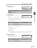
Page 200: ...mperature However when is set the afterheater does not work When temperature unit is Centigrade AFTERHEATER T 01 30 C When temperature unit is Fahrenheit AFTERHEATER T 01 086 F Parameter numeric input...

Page 201: ...tigrade temperature and Fahrenheit temperature is performed with 4 Temperature Unit in SETUP MENU P 3 59 Centigrade Fahrenheit conversion formula F 9 5 C 32 C 5 9 F 32 11 COLOR STRIPE Select whether t...

Page 202: ...atically correct the print quality or not IMAGE IMPROVE XX ON XX Selected media number Parameter choice input ON Automatic correction is performed Usually set to ON OFF Automatic correction is not per...

Page 203: ...rinting splicing appears on the printout However the image before and after the splice is once completed and then cleaning is performed The splicing can be corrected by P 3 40 15 BACK ADJUST VAL Selec...

Page 204: ...to prevent nozzle out of the print head Normally set it to 0000CYCLES PH REST PERIOD XX 0000CYCLES XX Selected media number Set the number of scans for print length in 16 PH REST PERIOD Parameter num...

Page 205: ...Y8 Parameter numeric input 32 to 31 Note For how to set the reciprocating correction value refer to Setting media advance correction values P 2 38 19 BIDIR VALUE3 The reciprocating correction adjusts...

Page 206: ...g media advance correction values P 2 38 21 SET REMAINING MEDIA Set the remaining media When the remaining media is set beforehand you can check the remaining media by subtracting the printed length i...

Page 207: ...TYPE02 OK 23 COPY MEDIA Select the media number of copy source Use this menu to copy the media information parameters of the registered media to other media Designate the copy destination in 24 PASTE...

Page 208: ...media information The parameters to be copied are setting content of 2 to 21 in MEDIA REG MENU To use the function to copy the registered media information the parameters for 23 COPY MEDIA and 24 PAST...

Page 209: ...2 Select the copy destination The value 13 displayed on the left side is the media number of copy source and the value on the right side is the media number of copy destination Select the media number...

Page 210: ...3 46 M ADV MENU Set parameters for media advance adjustment To set parameters press the key INK MEDIA REG MEDIA M ADV MEDIA ADV PRINT ROUGH NORMAL...

Page 211: ...Parameter choice input Explanation for media advance correction pattern To obtain a rough value NORMAL1 ROUGH NORMAL1 The media advance correction pattern is printed within a range of 99 0 to 101 0 in...

Page 212: ...L Parameter choice input NORMAL1 Selected when adjusting in the NORMAL1 or DENSITY2 print mode QUALITY Selected when adjusting in the QUALITY or DENSITY2 print mode DRAFT1 Selected when adjusting in t...

Page 213: ...ffline state menu mode PH REC MENU This menu is used to clean the print head of the printer Press the key to enter PH REC MENU for the print head REWIND FORM FEED PH REC PH MAIN PH RECOVERY NORMAL Par...

Page 214: ...o the offline state menu mode PH MAIN MENU This menu is used for the maintenance and replacement of the capping unit and the wiper blade as well as for cleaning the ink flow path Press the key to oper...

Page 215: ...to solve the nozzle out by charging wiper cleaning liquid to the cap after confirming that the nozzle out was not solved by several head cleanings The operation to charge the wiper cleaning liquid to...

Page 216: ...is provided to fill the cap with ink so that the print head nozzle surface is soaked in the ink Leave the printer for 1 to 2 hours and check again If nozzle out is not rectified even after cleaning i...

Page 217: ...NT 1 Menu print Used to print the printer information and operation panel setting information CONFIG PRINT Parameter execution method None 2 Error log print Used to print the error log information sav...

Page 218: ...S NOZZLE PRINT Parameter choice input NOZZLE PRINT Print the nozzle check pattern ADJUSTMENT CHECK Print the adjustment check pattern PH TO PH Print the head position adjustment pattern PH R L ADJ PRI...

Page 219: ...ns of each print head Enter the value where the vertical lines of each color align based on the print result of the right and left adjustment pattern P 2 43 Adjusting the print head nozzles position A...

Page 220: ...e media Enter the correction value based on the print result of EDGE SENSOR ADJ PRINT P 2 92 Correcting the edge sensor position EDGE SENSOR ADJ VAL 0 0mm Parameter numeric input 5 0 to 5 0 mm Note Re...

Page 221: ...Select the language of messages used for LCD LANGUAGE JAPANESE Parameter choice input JAPANESE The LCD message is displayed in Japanese ENGLISH The LCD message is displayed in English FRENCH The LCD...

Page 222: ...added 11 hours to the GMT as local time 01 Sets the time added 1 hour to the GMT as local time 00 Sets the GMT as local time 01 Sets the time subtracted 1 hour from the GMT as local time 11 Sets the...

Page 223: ...a jam error during printing BEEP UNCAP CARRI ON Choice Description Remarks ON Emits a warning beep OFF Does not emit a warning beep This setting is applied to the following states Cap cleaning Occurre...

Page 224: ...sion Displays the BOOT version BOOT VERSION X XX 9 F W Version Displays the system firmware version PRINTER FW VER X XX_YY 10 IPB Version Displays the version of the IPB board MAIN PCA VER XXXXX 11 AC...

Page 225: ...Displays the transfer speed of USB connection USB SPEED HIGH SPEED Choice Description Remarks HIGH SPEED Connected at HIGH SPEED FULL SPEED Connected at FULL SPEED 16 Initial Setting Sets all paramet...

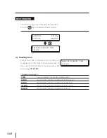
Page 226: ...f the heater including the time for transition to the standby set temperature after printing P 2 104 HEATER STANDBY TIME 30 min Parameter choice input 0 MIN Does not maintain the standby set temperatu...

Page 227: ...describes details of print mode and overview of special printing such as double sided printing Content of this section Print mode and special printing 4 2 Double sided printing 4 4 4 Printmodeandspec...

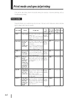
Page 228: ...6 NORMAL1 3 Normal mode Normally used mode This is the normal print mode Use this print mode normally The print quality is processed with a high resolution 30m2 h 60m2 h 720 x 720 8 NORMAL2 4 Solid pr...

Page 229: ...edia normally the whole image is printed with a slightly high density At the other modes the image is printed as follows The image such as photo is printed with the same density The solid painted part...

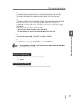
Page 230: ...MEDIA ROLL SHEET FACE to P 2 7 Media installation and removal At this time choose FACE with the or key for media selection Note When using banner with different undulations on the first and 2nd sides...

Page 231: ...ia it is recommended that you mark the position of the reference solid line at both sides of the 2nd side Reference dashed line for cutting Reference solid line on the 2nd side Note The drying time of...

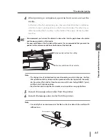
Page 232: ...a end under the interleaf Note If the media is set with a distortion or wrinkles this may cause a media jam or skew 8 Insert the media into the paper feeder and align the reference solid line at the e...

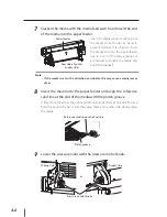
Page 233: ...l roller Put the supply side tension bar on the slack of the media at the supply side P 2 7 Roll media installation procedure step 18 Peel roller Scroller Media in general Tension bar with a flange Pr...

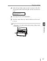
Page 234: ...s not proceed to the next operation CHECK SLACKEN MEDIA 15 The media setting operation starts automatically When the media setting is successfully completed the printer returns to the online or offlin...

Page 235: ...4 Print mode and special printing Double sided printing 16 Start printing on the 2nd side of the media Note Note that the data transfer from the RIP differs by 180 degrees between first side and 2nd s...

Page 236: ...4 10...

Page 237: ...aler from whom you purchased the product or our service depot nearest to you Content of this section When encounting a problem 5 2 How to clear media jams 5 6 When an error message is displayed 5 8 Wh...

Page 238: ...heated during printing or when the heater is turned on with the heater control menu Print an image or set the heater to ON to see if the paper guide is heated P 2 101 Changing temperature using the he...

Page 239: ...the print head P 2 95 Print head cleaning Although the printer is in the print mode printing does not start with PREHEATING displayed on the operation panel Inspection check item Action Room temperat...

Page 240: ...an power If the suction fan power is not best set reduce the power P 3 36 SUCTION FAN LEVEL Heater temperature setting If the heater temperature is not best set lower the heater temperature P 2 101 Ch...

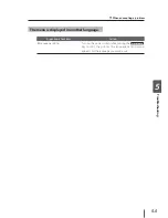
Page 241: ...problem The menu is displayed in another language Inspection check item Action Language setting Turn on the power switch while pressing the M E N U key to start the printer The language setting menu a...

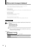
Page 242: ...is invalidating the printer s normal operation 2 Media jam 2 The media was not detected correctly because Roll media or cut sheet media was selected incorrectly The length of the applied cut sheet med...

Page 243: ...he carriage path and the media feed path and then close the front cover CARRIAGE MOVING PLEASE WAIT 4 The carriage moves to the home position 5 Install the media following Media installation and remov...

Page 244: ...message displayed on the LCD Service call errors When the following service call error appears reboot the printer by turning off and on the following Operation panel s power switch Rear panel s printe...

Page 245: ...pecified color is installed the ink pack may not be installed properly Check whether it is installed properly CHECK nn XXX INK PACK nn Ink error code XXX Ink color location Meaning A problem occurred...

Page 246: ...eaning A problem occurred with the subcartridge or the genuine ink pack cannot be recognized Action Take appropriate actions according to the message CHECK COLOR XXX SUBCARTRIDGE XXX Ink color locatio...

Page 247: ...curs when an obstacle is left in the media feed path and the printer cannot feed the media normally Action Take appropriate actions according to the message If the media jam 0 error occurs repeatedly...

Page 248: ...LOAD MEDIA Meaning Media is exhausted or the flange is not attached correctly to the flange holder Action When there is no media install new media If the flange is not attached correctly attach it co...

Page 249: ...OOLING PROCESS PLEASE WAIT Meaning The temperature of the print head is outside the operating temperature range Action Use the printer within the operating temperature range Leave the printer until th...

Page 250: ...ore ink charging is completed Perform ink charging OPEN COVER TO ATTACH SPITTOON CASE Meaning The uninstallation of the tray was detected when the printer was booted or when the cover was closed Actio...

Page 251: ...US belt and supply tube pump assembly is coming close Action Ask the service depot to replace them REPLACE WIPER BLADE Meaning The life of the wiper blade is coming close Action Execute REPLACE WIPER...

Page 252: ...ways necessary to solve the problem The print is light Cause Action The operating environment is outside the specification of the printer Raise the ambient temperature to more than 15 C 20 to 25 C rec...

Page 253: ...platen 2 Perform the daily maintenance P 2 108 3 Perform print head cleaning NORMAL ALL P 2 95 and then perform nozzle print to check that nozzle missing has been improved P 3 54 4 Perform the fillcap...

Page 254: ...and print the media P 3 38 2 Print the media in the QUALITY print mode P 4 2 Media feed is not adjusted properly Hint for media advance correction value P 5 23 1 Set the print quality mode to ON and p...

Page 255: ...media with proven media Ink drooling 1 Check the media for wrinkles or float or oblique setting and then reinstall the media if necessary P 2 7 2 Perform print head cleaning NORMAL ALL P 2 95 3 Perfo...

Page 256: ...2 When the printer is in the DENSITY print mode change the print mode to QUALITY P 4 2 Print head position s misalignment Print head bi directional position s misalignment 1 Adjust the print head pos...

Page 257: ...on the platen is near the suction hole the printer sucks a part of ink charged out between the media and the media edge guard which produces vertical stripes in some cases 1 Shift the media so that t...

Page 258: ...r roll media state If the roll media is not well finished replace it with a good one 2 Check whether the media is set straight to the printer If it is set obliquely raise the pressure roller with the...

Page 259: ...edia advance correction value differs with the number of paths of the print mode The same media advance correction value can be used for the same number of paths even in different print mode P 4 2 App...

Page 260: ...5 24 When abnormal sound is produced When you hear abnormal operating sound contact the sales dealer or our nearest service depot...

Page 261: ...the flat floor Do not move the printer with the scroller attached The printer may be damaged due to the weight of the media Loose and raise the adjustable leveling feet at the bottom of the printer b...

Page 262: ......

Page 263: ...s section describes the basic specifications and components of the printer and service depots Content of this section Basic specifications A 2 Footswitch option A 3 Exhaust attachment option A 5 Appen...

Page 264: ...charging noise Calorific power 15552000 J H Guaranteed print area Area excluding top bottom margins 5 mm and right and left margins 5 mm When media edge guards are used right and left margins are 10...

Page 265: ...mark Attaching footswitches do not increase power consumption Usage notes Do not use footswitches in a humid place or a place exposed to water to prevent a failure Do not connect or disconnect the foo...

Page 266: ...re installing the footswitch Plug the other connector of the footswitch in the connector of the take up reel unit and then screw the ground line Loosen the screw fixing the cable clamp to the printer...

Page 267: ...Ventilation of the room is necessary regardless of whether the exhaust attachments are used Components Exhaust attachment 2 pieces Exhaust attachment mounting screw 12 pieces Installation Attach two e...

Page 268: ......

Reviews: