Tel: 886.2.2175 2930 Email: [email protected]
www.salukitec.com
205
Display or edit the characteristic description of the calibration kit.
2) Connector type zone
a) [Connector] box
Click the [Connector] box or arrow button to select the connector type.
b) [Add] button
Click the [Add] button. The [Add connector] dialog box will appear. Add the new connector type of the calibration kit.
c) [Modify] button
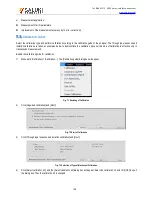
The [Modify connector name] dialog box will appear. Modify the connector name.
Fig. 7.11 [Change connector name] Dialog Box
3) Type zone
a) [Calibration method] box
Click it to select the calibration method corresponding to the type.
b) [Edit type] button
Click it and the [Type information] dialog box to set the type of the calibration kit.
4) Standard zone
a) [Calibration kit] box
Display the ID, name and description of the calibration kit supported by the analyzer at present.
b) [Add] button
The [Add standard] dialog box will appear. Add the new definition of calibration standard.
c) [Edit] button
Click it and the [Standard calibration kit (such as the open-circuit device, short-circuit device, load, through type connector/air
line/adapter)] dialog box will appear. Modify the definition of the selected standard calibration kit.
d) [Delete] button
Delete the definition of the selected standard calibration kit.
e) [Delete all] button
Delete the definitions of all standard calibration kits.
f)
[
∧
] and [
∨
] button
Select the standard calibration kit.


