


Tel: 886.2.2175 2930 Email: [email protected]
www.salukitec.com
173
The electrical delay is a kind of mathematical function. The transmission line of no loss and adjustable length can be simulated.
The electrical delay which is not associated with each measurement trace can be set.
6.5.2.
Port Extension
1) The measurement reference plane can be moved electrically by means of port extension after calibration. Thus, other kinds of
calibration can be avoided. Port extension is introduced in the following two cases.
a) Decide whether to add one cable in the measurement configuration after calibration. The port extension characteristics can
be applied to “tell' the analyzer to increase the cable length to the specific port.
b) If calibration cannot be done directly on the tested device in the test fixture, port extension can be applied to compensate
the delay (phase offset) arising from the fixture.
2) Use of port extension function
a) If the electrical length of the tested fixture or added cable is known, enter the value in the [Time] box.
b) If the physical length of the tested fixture or added cable is known, enter the value in the [Distance] box.
c) If the above two items are unknown, the open-circuit device or short-circuit device can be used instead of the tested device
on the reference plane after extension. Generally, the new reference plane is regarded in the open- circuit state after
removal of the tested device.
3) The appropriate port extension value can be obtained in the following methods.
a) Select the S11 measurement after calibration and set the phase format as the display format.
b) Connect the open-circuit device or short-circuit device to the calibration plane and check whether the displayed phase curve
is within the measurement frequency range and around 0°.
c) Connect the fixture or transmission cable and use the open-circuit device or short-circuit device instead of the tested device
(the circuit is regarded as an open circuit if the tested device is removed). Adjust the value of
d) the [Time] or [Distance] box in the [Port extension] dialog box until the phase trace is flat.
e) If the loss characteristics of the extension part are known, compensation can be done in the one-dimensional or
two-dimensional manner in the [Loss compensation] part.
Nonzero delay
The nonzero delay is specified in the majority of short circuit standards and can be applied to adjust the error which is twice that of
short-circuit calibration as a result of port extension and further view the definition of the calibration kit so as to determine the
appropriate extension value.
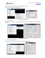
4) Setting of port extension
Menu path: [Calibration] > [Port extension].


