


Tel: 886.2.2175 2930 Email: [email protected]
www.salukitec.com
172
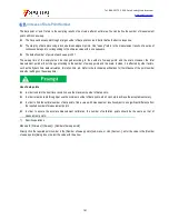
Fig. 6.6 Schematic Diagram of Test of Long Cable
The delay of the electrical long device can be compensated in the following methods.
1) Reduction of sweep speed
The sweep speed can be reduced by increasing the scanning time, reducing the IF bandwidth or increasing the number of sweep
points.
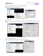
a) Increase the sweep time.
Menu path: [Stimulus] > [Sweep] > [Sweep time...]. Enter the time or select the time with the arrow.
b) Reduce the IF bandwidth.
Menu path: [Response] > [Average] > [Intermediate frequency bandwidth...]. Directly enter the value or select the time with the arrow.
c) Increase the number of sweep points.
Menu path: [Stimulus] > [Sweep] > [Number of sweep points].
Directly click the required point number in the sub-menu or click [Custom...]. Enter the value in the [Number of sweep points] dialog
box or select the value with the arrow.
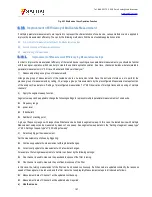
2) Use of step sweep.
Change analog sweep into step sweep so that the source can step over each test point. In this case, the
sweep speed of the analyzer can be reduced. The dwell time of each step or test point can also be set. Menu path: [Stimulus] >
[Sweep] > [Sweep setting...].
Tick the step sweep Directly enter the dwell time in the [dwell time] box or select the required dwell time
of each test point.
6.5.
Improvement of Phase Measurement Accuracy
The following characteristics of the analyzer can be applied to improve the accuracy of phase measurement.
Electrical delay
Port extension
phase offset
Frequency point interval
Specific operation
6.5.1.
Electrical Delay
The electrical delay can be applied to compensate the linear phase offset of the tested device so as to highlight the linear phase
offset of the tested device.


