58
b) Performing a Function Inspection of the Steering
• Support the model at the front in a way that allows the wheels to hang freely.
Due to the good traction of the wheels and the weight of the vehicle, the wheels would not follow your steer-
ing commands spontaneously and directly while still on the floor. This changes during operation.
• First switch on the transmitter, then the receiver power supply.
• Move the steering wheel at the transmitter to the left and right.
• The wheels must deflect to the left and right (in the same direction in which you turn the steering wheel).
If the wheels move in the opposite direction, switch the reverse function for the steering into the respective other
position and check the starting function again.
• Release the steering wheel (neutral position); now the wheels must return to the straight position. If the wheels do
not stop straight in the neutral position of the steering wheel, correct this with the trim function of the steering at your
transmitter. The steering wheel end stops left/right should lead to left/right end stops of the steering.
Observe:
The precise alignment of the steering for straight driving is performed later during driving, using the trim
function at the transmitter. Therefore, it is no required that you align the wheels 100% while standing.
c) Function of Linkage of Carburettor and Brake
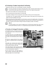
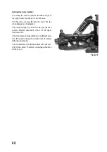
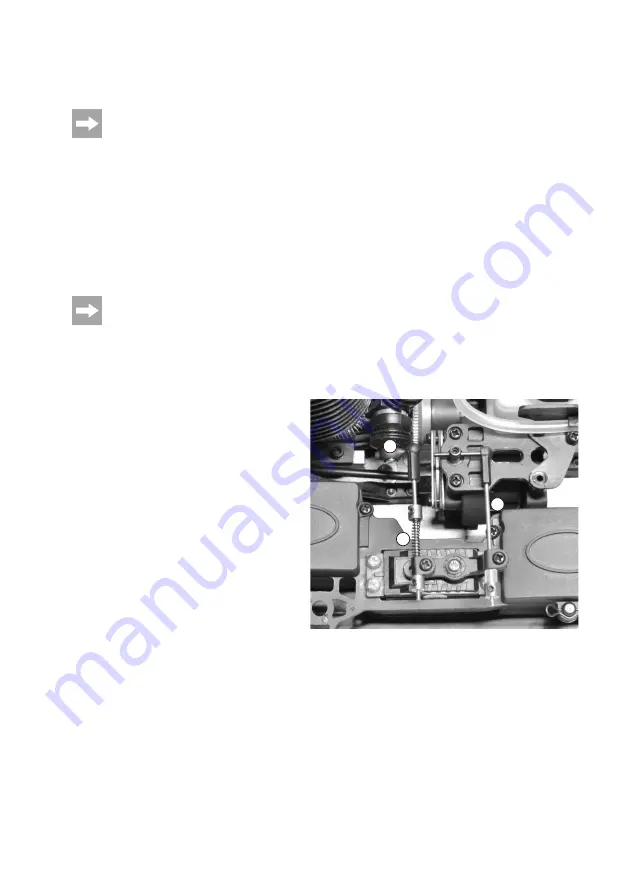
The throttle/brake servo is connected to channel 2 of
the receiver and is moved by moving the finger grip
at the transmitter.
The special placement of the throttle/brake linkage
leads to two functions being carried out at the same
time via two servo steering levers that are offset by
90°.
By moving the carburettor slide (B), the air supply to
the engine is controlled through the throttle linkage
(A).
At the same time, the idling nozzle needle (conical
needle of a needle valve) is moved to change the fuel
amount flowing through the carburettor.
If the throttle linkage is pushed beyond the idle posi-
tion (mechanic end stop of the carburettor slider), the
servo arm pushes against a spring stop.
Now the sphere of action of the brake linkage (C)
comes into effect; it pushes the brake shoes of the
disk brakes together via an eccentric tappet.
Figure 5
A
B
C
Summary of Contents for 1456608
Page 154: ...154 ...
Page 155: ...155 ...

