57
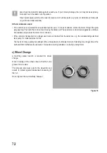
9. Technical Data
a) Steering Function
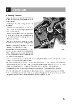
The steering servo is connected to channel 1 of the
receiver and is moved by turning the steering wheel
at the transmitter.
The steering of the vehicle is designed as an axle
leg steering.
The pivoting movement of the servo control lever (A)
has an effect on the steering linkage (B) and on one
arm of the servo saver (C).
The servo saver consists of two right-angled levers
(C and D), which are not rigidly coupled but can be
moved against each other via a spring on one level
with the steering linkage.
The second lever arm of the servo saver (D) moves
the middle part of the track rod, the steering plate (E).
It leads to a movement of the track rod (F), which
causes a steering deflection of the wheels.
When hard impacts are transmitted through the track
rod during operation, they are not immediately trans-
mitted to the steering servo, but are absorbed with
the help of the resilient connection of the two lever
arms (C and D) of the servo saver.
The servo saver effect can be set with a knurled nut (G). Twisting the knurled nut causes a change to the press-on
pressure on the two lever arms of the servo saver.
If the setting is too tight, the servo saver is rendered ineffective since the two arms of the servo saver cannot turn
against each other anymore. Too weak a setting has negative effects on driving behaviour, since, e.g., even small
potholes will strongly change the steering angle. The vehicle can barely be driven straight ahead here.
Turning left and right is limited by a mechanical stop of the steering knuckle arm against the axle leg support.
If the transmitter used permits, the servo path should be limited accordingly to prevent the steering servo from block-
ing. This will not only cause a high power intake (and a quickly discharging receiver battery), but also overload of the
steering servo gear and possibly overheat and damage the steering servo electronics.
A
B
C
D
E
F
Figure 4
G
Summary of Contents for 1456608
Page 154: ...154 ...
Page 155: ...155 ...

